
Method for controlling an internal combustion engine using model based VGT/EGR control

a technology of internal combustion engine and control algorithm, which is applied in the direction of electrical control, process and machine control, etc., can solve the problems of poor responsiveness, relative sluggishness of air systems, and poor performance of conventional controllers when the engine is running poorly, so as to improve the transient state responsiveness of egr and/or vgt control system, improve the effect of egr and/or vgt control, and improve the effect of eg

Inactive Publication Date: 2008-01-22
DETROIT DIESEL CORP
View PDF16 Cites 7 Cited by
  • Summary
  • Abstract
  • Description
  • Claims
  • Application Information

AI Technical Summary

Benefits of technology

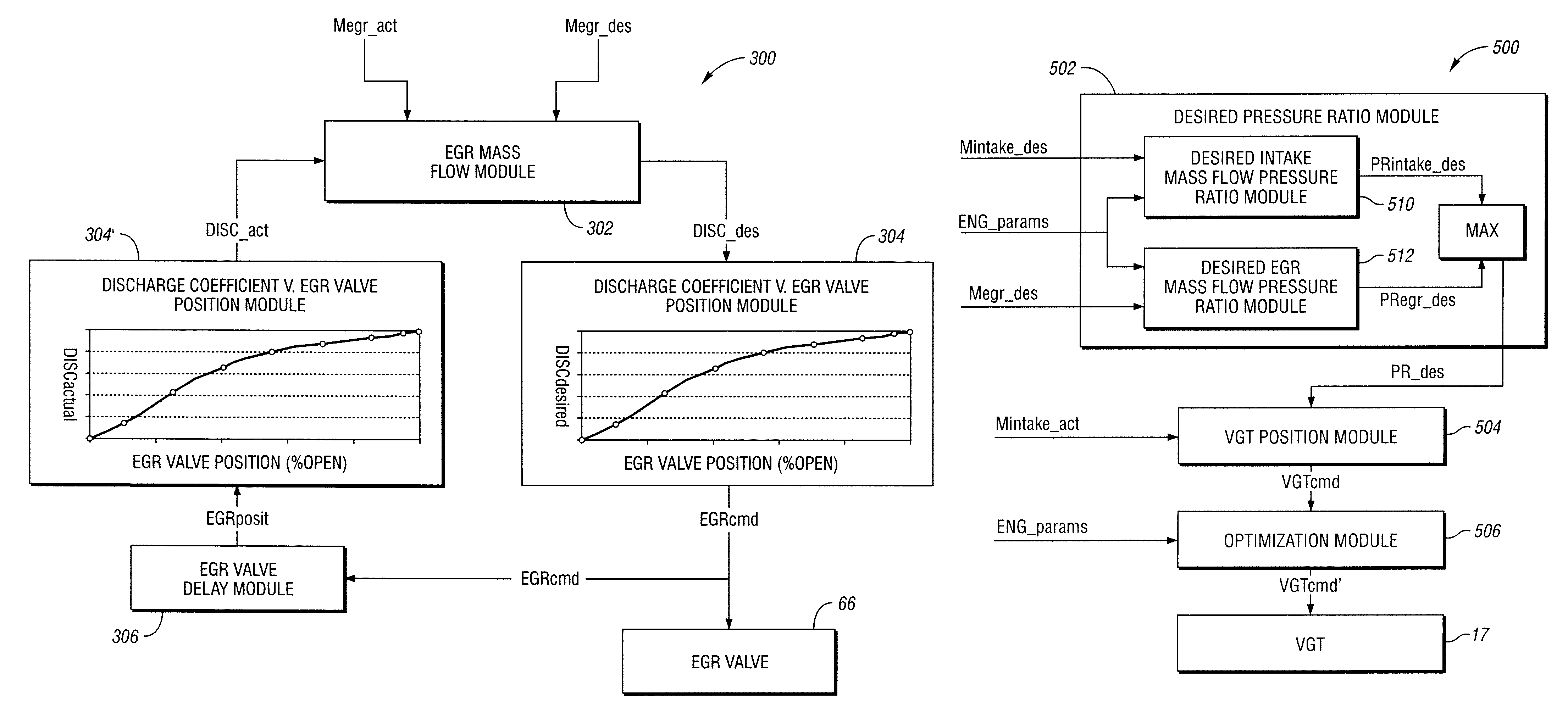
"The present invention provides an improved method for controlling EGR and / or VGT in an internal combustion engine. The method uses model-based control systems to separate control of turbine air mass flow and EGR mass flow, increase transient state responsiveness, reduce oscillation, and reduce or eliminate reverse EGR flow. The method includes generating desired EGR valve discharge coefficient and turbine pressure ratio based on engine parameters, and transmitting the desired EGR valve discharge coefficient and turbine pressure ratio to the EGR valve and VGT, respectively. The technical effects of the invention include improved EGR and VGT control during engine operation, including transient operation, and reduced reverse EGR flow."

Problems solved by technology

Such conventional controllers generally perform poorly when the engine is operating under transient conditions (e.g., up and down hills, in response to a varying load, idle to rapid acceleration operation, intermittent workpiece characteristics for power takeoff driven applications, etc.).
The poor responsiveness may be attributed to the relative sluggishness of air systems.
In the case of a PID based controller, the delay between the modification of the controlled parameter and the detection of a change in the system generally results in oscillation around a desired setpoint.
However, reducing the responsiveness generally provides inadequate performance when the system is operating in a transient state.

Method used


Image

  • Method for controlling an internal combustion engine using model based VGT/EGR control
  • Method for controlling an internal combustion engine using model based VGT/EGR control
  • Method for controlling an internal combustion engine using model based VGT/EGR control

Examples


Embodiment Construction

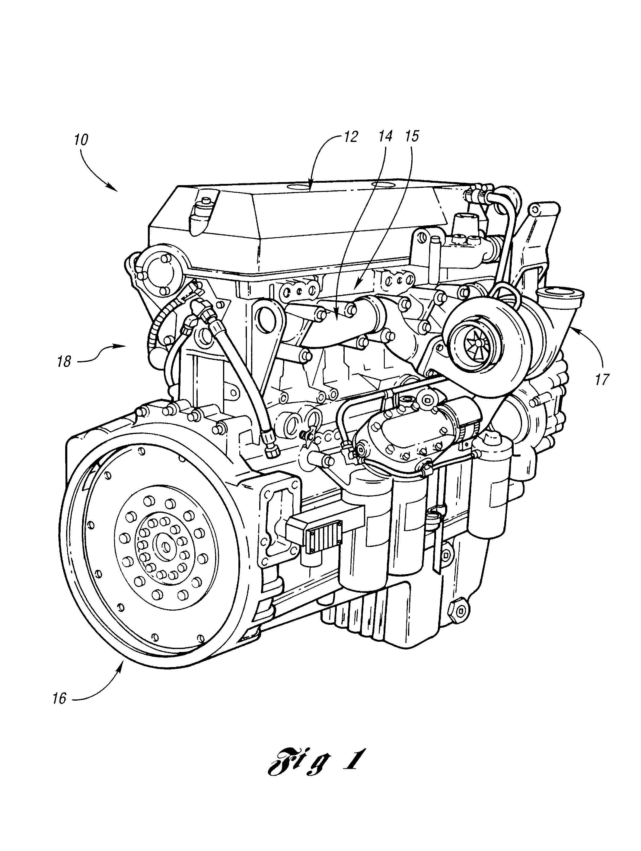
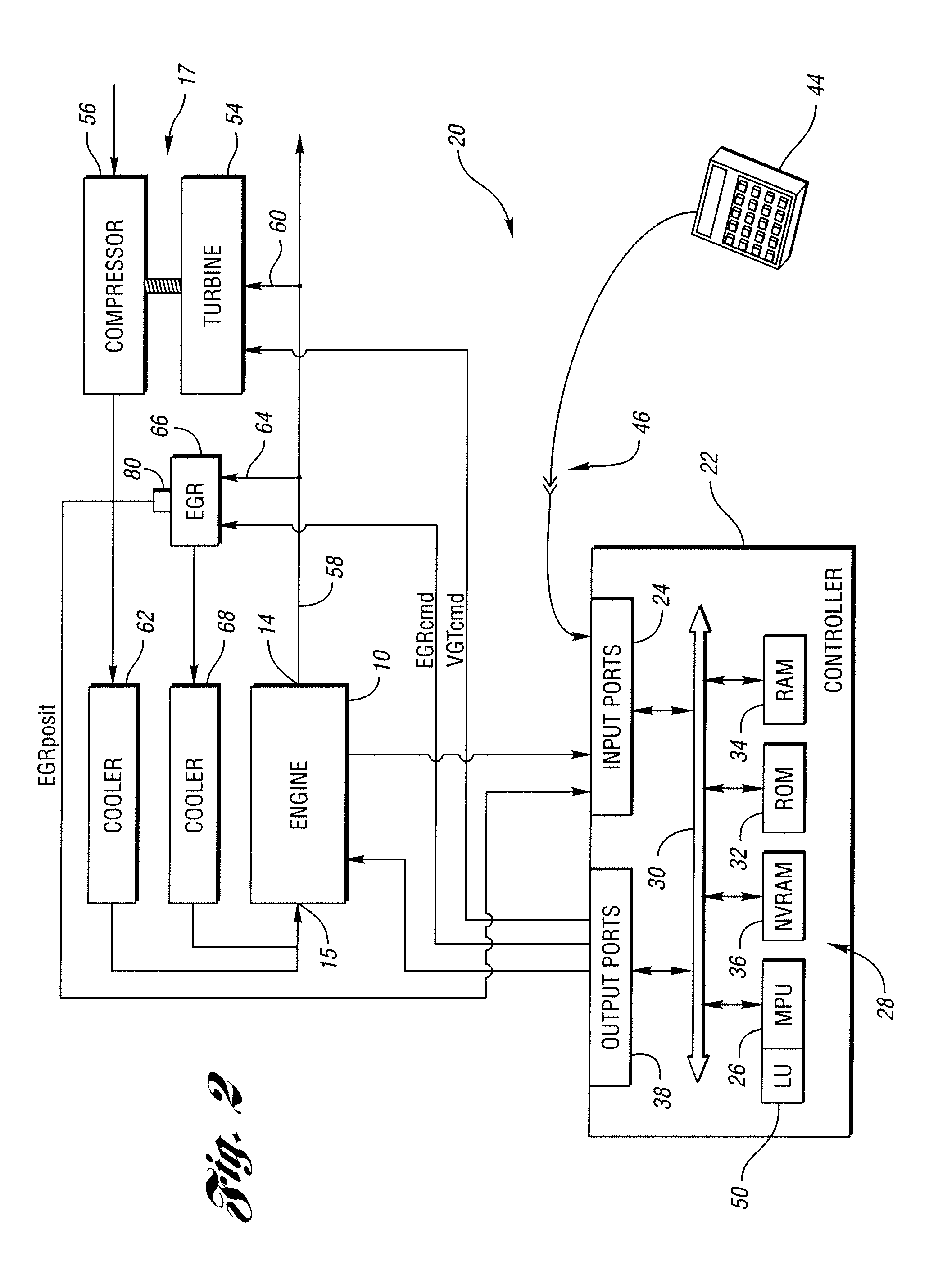
[0022]With reference to the Figures, embodiments of the present invention will now be described in detail. The present invention is generally implemented in connection with an internal combustion engine (e.g., a compression ignition or diesel engine) having exhaust gas recirculation (EGR) and / or variable geometry turbocharger (VGT) systems and may provide an improved method for EGR and / or VGT control using model based VGT / EGR closed loop control systems.

[0023]In the description below, these variable may be defined as follows:

CONair=Air gas constant

CONegr=EGR model constant

CPair=Air specific heat

DISC_act=Actual EGR valve discharge coefficient

DISC_des=Desired EGR valve discharge coefficient

Eturbo=Turbo power

IMP=Intake manifold pressure

IMT=Intake manifold temperature

Iturb=Turbo shaft moment of inertia

Mair=Air mass flow rate

Megr_act Actual EGR mass flow rate

Megr_des=Desire EGR mass flow rate

Mintake_act=Actual intake mass flow rate

Mintake_des=Desired intake mass flow rate

Ncomp_eff=Compre...


PUM


Abstract

A method for controlling an internal combustion engine using model based control, the engine including a variable geometry turbocharger (VGT) driven in response to a VGT command signal and / or an exhaust gas recirculation (EGR) valve driven in response to an EGR valve command signal to recirculate exhaust to an engine intake manifold.

Description

STATEMENT REGARDING FEDERALLY SPONSORED RESEARCH OR DEVELOPMENT[0001]The invention was made with Government support under Contract No. DE-FC05-00OR22805. The Government has certain rights to the invention.BACKGROUND OF THE INVENTION[0002]1. Field of the Invention[0003]The present invention relates to a method for controlling an internal combustion engine using a model based control algorithm, and in particular an internal combustion engine having an exhaust gas recirculation (EGR) and / or a variable geometry turbocharger (VGT) system.[0004]2. Background Art[0005]Internal combustion engines, and in particular, compression ignition (or diesel) engines have a wide variety of applications including passenger vehicles, marine vessels, earth-moving and construction equipment, stationary generators, and on-highway trucks, among others.[0006]Internal combustion engines may include exhaust gas recirculation (EGR) systems and / or variable geometry turbocharger (VGT) systems. Conventional EGR an...

Claims


Application Information

Patent Timeline
Patent Type & Authority Patents(United States)
IPC IPC(8): F02B33/44F02M25/07
CPCF02B37/22F02D23/02F02D41/0007F02D41/0072F02B3/06F02B29/0406F02B39/16F02D41/0077F02D2041/1433F02M25/0707F02M25/0713F02M25/0727F02M25/0756Y02T10/144Y02T10/47F02D2041/1431F02M26/05F02M26/10F02M26/23F02M26/48Y02T10/12Y02T10/40
Inventor SUN, MIN
Owner DETROIT DIESEL CORP
Learn More