
Device for continuously filtering material mixtures

a technology of material mixture and filter body, which is applied in the direction of filtration separation, separation process, chemistry apparatus and processes, etc., can solve the problems of accelerated wear, loss of effectiveness, and increased friction between the filter body and the stripper, so as to improve the stability of the device, reduce wear, and simplify the effect of filtering

Active Publication Date: 2007-03-29
ETTLINGER KUNSTSTOFFMANSCHINEN GMBH +1
View PDF6 Cites 6 Cited by
  • Summary
  • Abstract
  • Description
  • Claims
  • Application Information

AI Technical Summary

Benefits of technology

"The invention is a device that improves the removal of residue from a filter. It automatically adjusts the contact pressure of the stripper to the actual conditions, reducing friction and wear. The residue is lifted from the filter surface in a radial direction, making it easier to discharge and improving stability. The material lifted by the stripper is transported away by a spiral conveyor, which can be controlled separately for cleaning and foreign material discharge speed. This allows for a high impurity concentration and optimizes the filter surface. The device can be controlled using a hydraulic pressure transducer or an electronic pressure transducer."

Problems solved by technology

However, to enable continuous and uninterrupted filtering, the melt filter must be cleaned continuously.
However, in such elastic contact of the strippers, there is the problem that the strippers can he lifted from the surface of the filter body due to the pressure of the plastic melts and thereby lose their effectiveness.
On the other hand, too high a contact pressure leads to increased friction between the filter body and the strippers, which is associated with accelerated wear.

Method used


Image

  • Device for continuously filtering material mixtures
  • Device for continuously filtering material mixtures
  • Device for continuously filtering material mixtures

Examples


Embodiment Construction

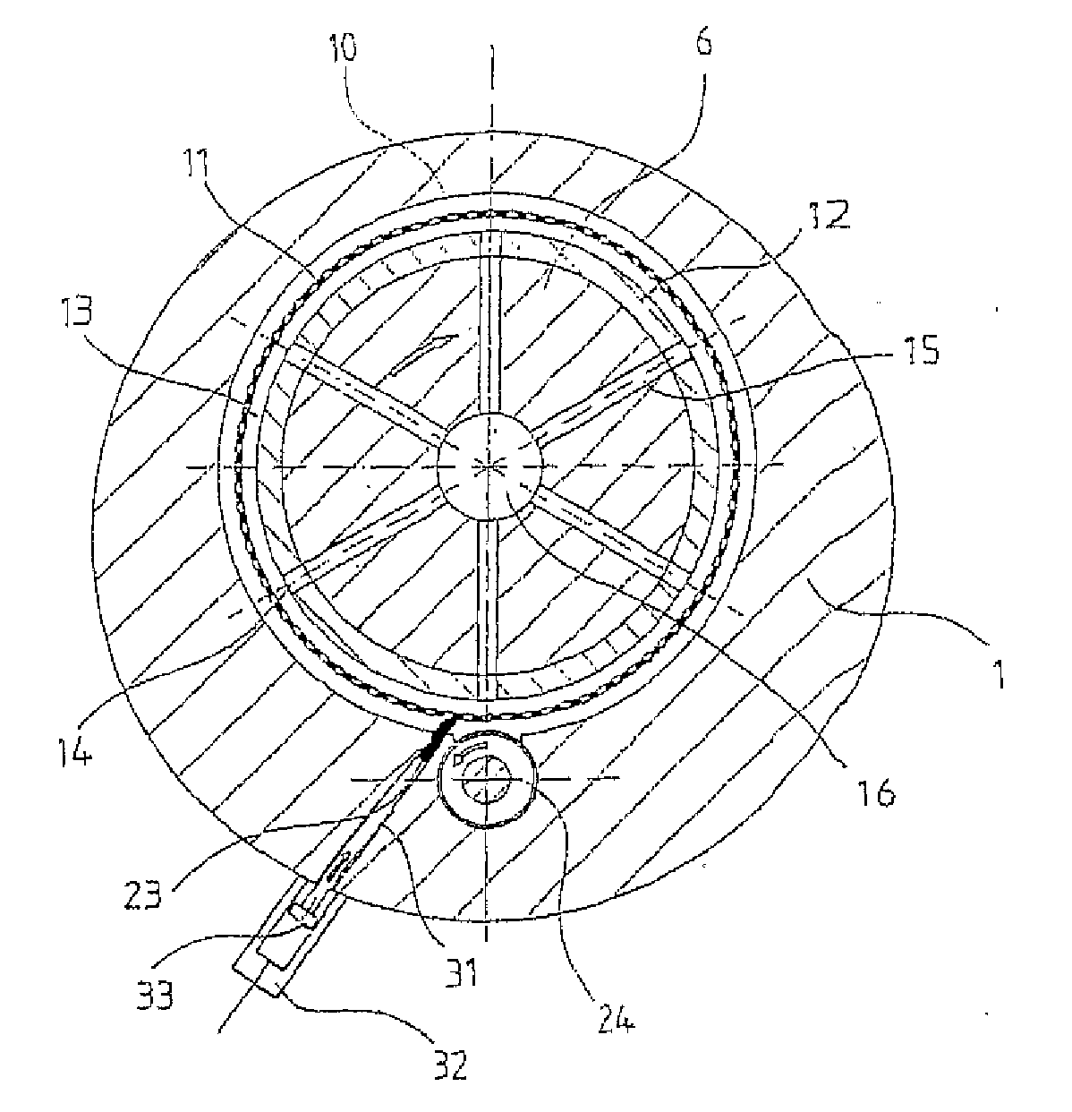
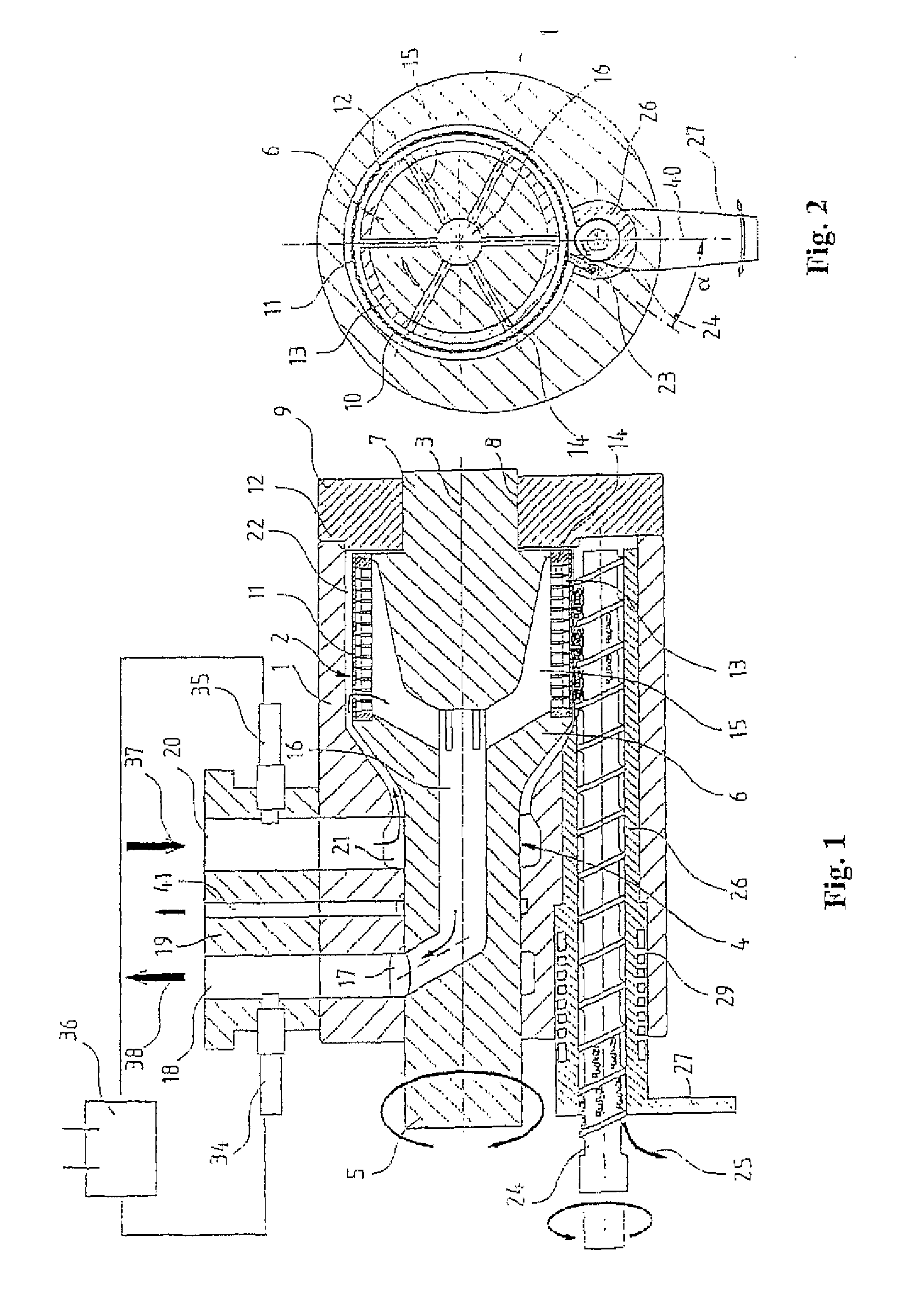
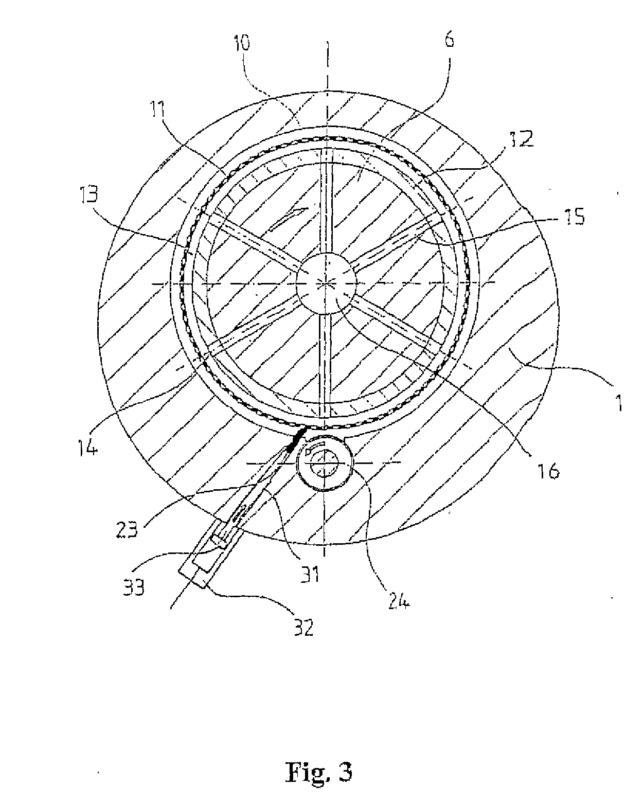
[0017] The filter device shown schematically in FIG. 1 for filtering contaminated plastic melts includes a housing 1, in which a hollow, cylindrically-shaped filter element 2 is rotatably arranged about a center axis 3. The filter element 2 is mounted on a motor-driven carrier shaft 4. This includes a narrow driving part 5 mounted in the housing 1, a wider holding part 6 for the melt filter 2, and a narrow bearing journal 7, which is rotatably mounted in a corresponding bore 8 of a bearing cover 9 fixed on the housing 1.

[0018] The filter element 2 comprises a filter tube 11 provided with a plurality of radial through-holes 10 and a hollow, cylindrically-shaped support body 12, which is connected to the carrier shaft 4 with a positive fit and onto which the filter tube 11 is shrunken. The sieve-like filter tube 11 can be produced, e.g., from a steel sheet, which has through-holes 10, which is bent and then welded into a tube. Preferably, it is made from a wear-resistant and corrosio...


PUM

PropertyMeasurementUnit
contact angleaaaaaaaaaa
pressureaaaaaaaaaa
contact pressureaaaaaaaaaa

Abstract

The invention relates to a device which is used to continuously filter material mixtures, in particular for separating impurities from plastic melts. The device includes a hollow cylindrically-shaped filter element (2) which is arranged inside a housing (1), an annular chamber (22) which is defined from the outside of the filter element (2) and an inner wall of the housing, and at least one stripper (23) which can be pressed onto the filter body by means of an adjusting device. The stripper is used to remove the impurities detained on the filter element (2) due to a relative movement of the filter element (2) and the stripper (23). The adjusting device contains a pressure sensor (42, 53) which is used to detect the pressure of the material mixture upstream from the filter body and an actuator (43) which is connected to the pressure sensor, said actuator being used to adjust the pressure of the stripper (23) according to the pressure detected by the pressure sensor.

Description

FIELD OF THE INVENTION [0001] The invention relates to a device for continuously filtering material mixtures, particularly for separating impurities from plastic melts. BACKGROUND OF THE INVENTION [0002] Used plastics or plastic waste typically have high percentages of foreign materials, e.g., metal parts, paper residue, glass, secondary plastics, and the like. Usually, these foreign materials or impurities must be removed before the plastics are reused. This is realized in several ways such that the used plastics are first plasticized by heating and the plastic melts are then filtered. For this purpose, so-called melt filters are used, through which the metallic or non-metallic foreign materials or higher melting point plastics are separated. However, to enable continuous and uninterrupted filtering, the melt filter must be cleaned continuously. [0003] From U.S. Pat. No. 4,470,904, a separating device according to the class is known, in which the contaminated plastic melts are pres...

Claims


Application Information

Patent Timeline
Patent Type & Authority Applications(United States)
IPC IPC(8): B01D33/00B01D33/073B29C48/03B29C48/694B29C48/92
CPCB01D33/073B29C47/0009B29C47/0888B29C47/687B29C2947/92019B29C47/92B29C2947/92523B29C2947/9299B29C2947/9238B01D33/466B01D33/808B29C48/92B29C48/03B29C48/2735B29C48/694B29C2948/92019B29C2948/9238B29C2948/92523B29C2948/9299B01D33/06
Inventor ETTLINGER, RODERICH
Owner ETTLINGER KUNSTSTOFFMANSCHINEN GMBH
Learn More