Method and apparatus to determine robot location using omni-directional image

a robot and omni-directional image technology, applied in the direction of vehicle position/course/altitude control, process and machine control, instruments, etc., can solve the problems of difficult for a user to correctly recognize the location, user difficulty in recognizing the correct location of the robot, and inability to recognize the robot in real time. , to achieve the effect of easy processing of correlation coefficient and easy recognition

Active Publication Date: 2008-03-27
SAMSUNG ELECTRONICS CO LTD
View PDF5 Cites 56 Cited by
  • Summary
  • Abstract
  • Description
  • Claims
  • Application Information

AI Technical Summary

Benefits of technology

[0010]The general inventive concept provides a method to determine a robot location to easily process a correlation coefficient between an omni-directional image of an omni-directional camera mounted on a

Problems solved by technology

As a result, it is impossible to recognize the location of the robot in real time, and it is difficult for a user to correctly recognize the location of the robot due to accumulated errors encountered by the increased number of calculations.
In addition, t

Method used


Image

  • Method and apparatus to determine robot location using omni-directional image
  • Method and apparatus to determine robot location using omni-directional image
  • Method and apparatus to determine robot location using omni-directional image

Examples


Embodiment Construction

[0043]Reference will now be made in detail to the embodiments of the present general inventive concept, examples of which are illustrated in the accompanying drawings, wherein like reference numerals refer to like elements throughout. The embodiments are described below to explain the present general inventive concept by referring to the figures.

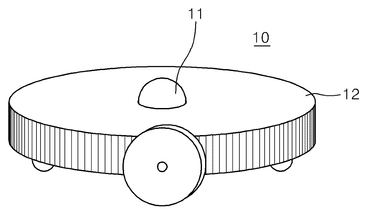
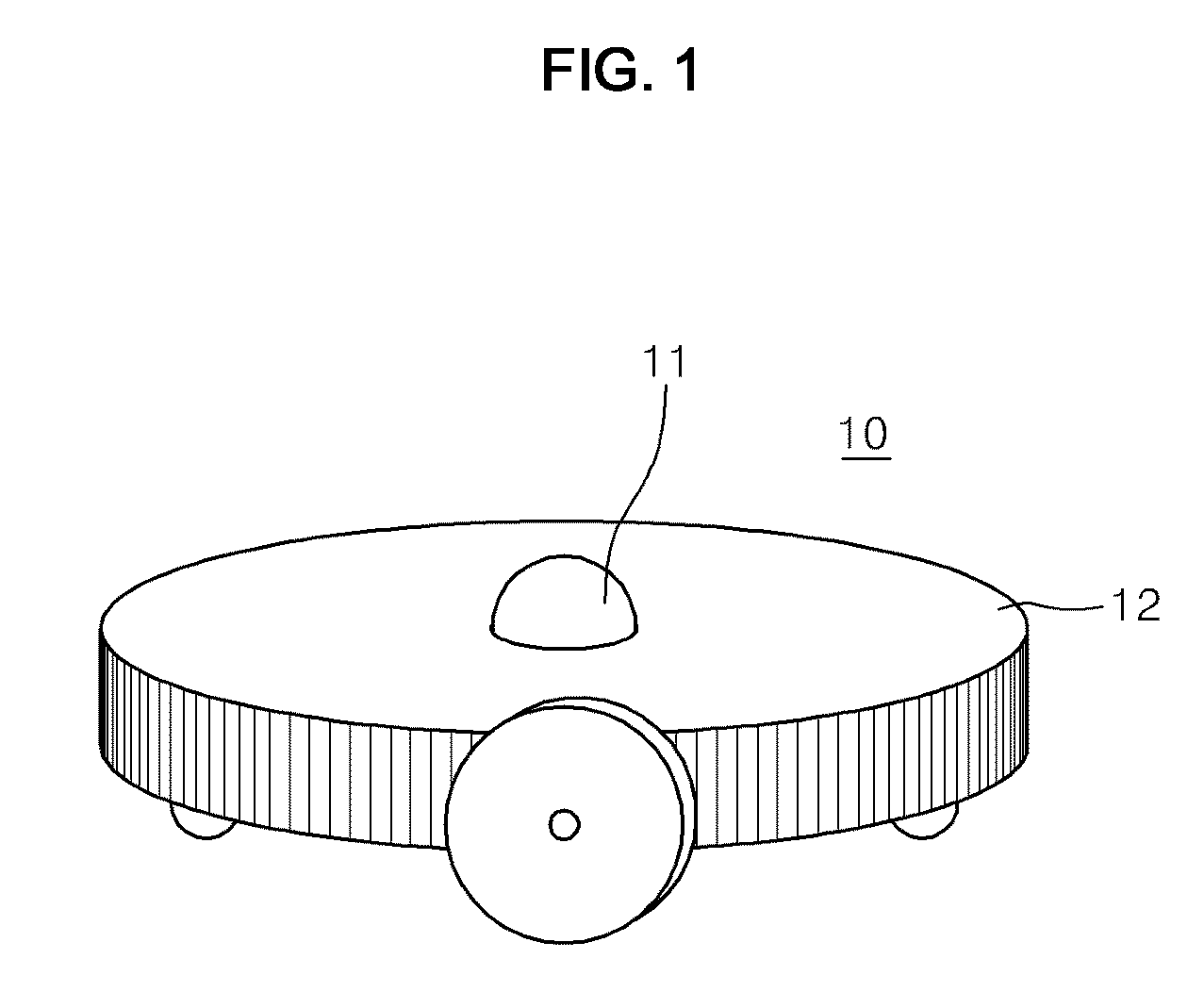
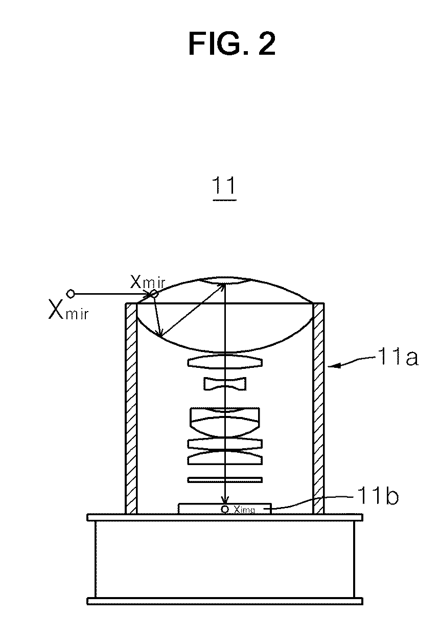
[0044]Referring to FIGS. 1 and 2, a moving robot equipped with an omni-directional camera 10 may include an omni-directional camera 11 and a robot body 12. The omni-directional camera 11 may include an omni-directional lens 11a and a CCD element 11b.

[0045]Referring to FIG. 2, a curved mirror can be attached to a front part of the omni-directional camera 11, such that an image of 360° in a vicinity of the omni-directional camera 11 can be acquired. As denoted by an arrow direction, a spatial point Xmir is reflected at a specific point xmir located on the curved mirror, such that an image is formed on the CCD element 11b, resulting in the occ...


PUM


Abstract

A method to determine the location of a robot using an omni-directional image, the method including acquiring an omni-directional image from a robot, extracting a predetermined current line from the acquired omni-directional image, calculating a correlation coefficient between the extracted current line of the robot and each landmark line of pre-stored nodes using a Fast Fourier Transform (FFT), and performing a stochastic approach method of a particle filtering process on a basis of the calculated correlation coefficient to recognize a location of the robot.

Description

CROSS-REFERENCE TO RELATED APPLICATIONS[0001]This application claims priority under 35 U.S.C. §119(a) from Korean Patent Application No. 2006-0093653, filed on Sep. 26, 2006 in the Korean Intellectual Property Office, the entire disclosure of which is incorporated herein by reference.BACKGROUND OF THE INVENTION[0002]1. Field of the Invention[0003]The present general inventive concept relates to a method and apparatus to determine a location of a robot (i.e., a method to locate the robot), and more particularly to a method and apparatus to determine the location of a robot using an omni-directional camera on the robot to acquire an omni-directional image.[0004]2. Description of the Related Art[0005]Generally, an omni-directional camera is adapted to acquire an omni-directional image, and can acquire an image of 360° in a vicinity of the camera.[0006]In recent times, the omni-directional camera is mounted to a moving robot in order to recognize a current location of the robot.[0007]A ...

Claims


Application Information

Patent Timeline
IPC IPC(8): G06K9/00
CPCG06K9/00664G06K9/00791G05D1/0246G06V20/10G06V20/56G06T7/40G06T7/00A47L9/28
Inventor YOON, SUKJUNEROH, KYUNG SHIKHAN, WOOSUPMIN, SEUNG KI
Owner SAMSUNG ELECTRONICS CO LTD
Why Eureka
Try Eureka