Vehicle recognizing apparatus

a recognition apparatus and vehicle technology, applied in the direction of vehicle components, cycle equipment, optical signals, etc., can solve the problems of difficult to arrange a number of infrared leds without detracting significantly from the aesthetic beauty of the vehicle, and achieve the effect of not affecting the beauty and design of the recognized vehicle, easy and quickly recognition, and high brightness

Active Publication Date: 2010-02-02
HONDA MOTOR CO LTD
View PDF21 Cites 3 Cited by
  • Summary
  • Abstract
  • Description
  • Claims
  • Application Information

AI Technical Summary

Benefits of technology

[0008]An object of the present invention is to solve the aforementioned problems of the conventional technologies and to provide a vehicle recognizing apparatus which does not require a sophisticated image processing function in a vehicle on the recognizing side, which can be easily applied to a two-wheeled vehicle as a recognized vehicle, and which does not mar the beauty and design of the recognized vehicle.
[0009]To achieve the aforementioned object, in a vehicle recognizing apparatus causing the presence of a vehicle equipped with the apparatus to be recognized by others therearound, the present invention includes at least three infrared markers emitting infrared light; and a drive circuit causing each of the infrared markers to emit light. The three markers are distributed and placed at respective vertices of a virtual triangle in at least one of front and rear views of the vehicle, and the first and second infrared markers are distributed and placed at a pair of right and left vehicle components. This triangular arrangement allows vehicles having such a device to be readily discerned from other infrared sources. Exemplary embodiments include first and second infrared markers distributed and placed at right and left side-view mirrors, at right and left turn-signal lights, at right and left handle grip ends, at right and left turn-signal light stays, near right and left edges of a front cowl, or near right and left edges of a handle cover. Mounting the infrared sources in these locations allows for distributed infrared sources without the expense of providing an additional framework for their mounting. In addition, a headlight may be disposed within a triangle with vertices at the three infrared markers, which allows the infrared markers to be easily and quickly recognized by preferentially searching an area around the headlight, which has high brightness and can be easily recognized.

Problems solved by technology

However, when the preceding or oncoming vehicle is a two-wheeled vehicle, it is difficult to locate the infrared LEDs so that an accurate vehicle distance and relative motion can be determined.
Furthermore, it is difficult to arrange a number of infrared LEDs without detracting significantly from the aesthetic beauty of the vehicle.

Method used


Image

  • Vehicle recognizing apparatus
  • Vehicle recognizing apparatus
  • Vehicle recognizing apparatus

Examples


first embodiment

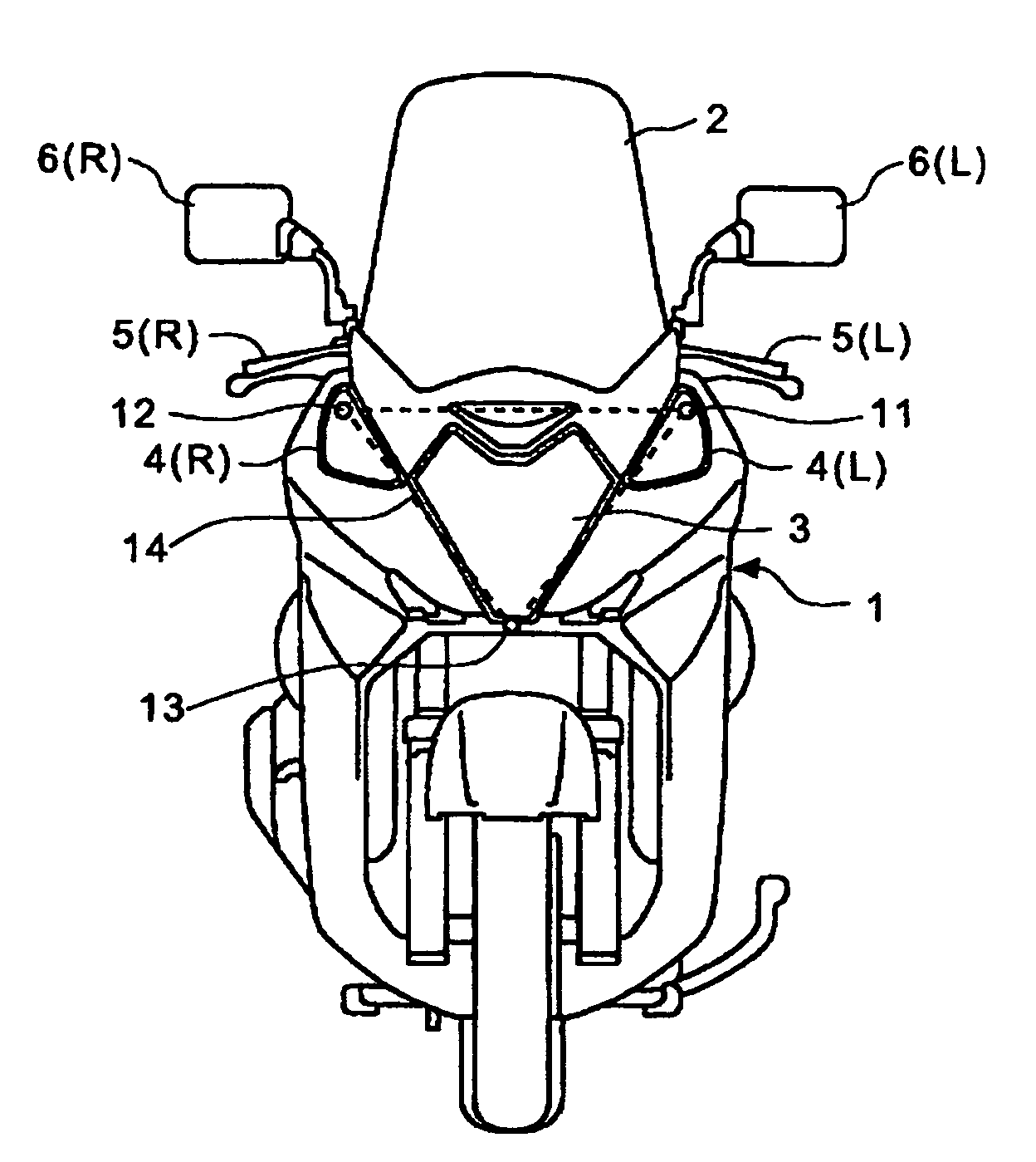
[0023]Referring now to the drawings, wherein like reference numerals generally designate identical or corresponding parts throughout the several views, and more particularly to FIG. 1A, there is shown a front view of a motorized two-wheeled vehicle with a vehicle recognizing apparatus according to the present invention. Same reference numerals in the various Figures indicate similar portions.

[0024]A front cowl 1 is attached to front part of a vehicle body, and a windshield 2 is attached to a V- or U-shaped open notch portion of an upper part of the front cowl 1. A headlight 3 is equipped at a center top part of the front cowl 1, and a pair of left and right turn-signal lights 4 (L, R) are equipped at both ends of the front cowl 1 with the headlight 3 interposed therebetween. Each of the headlight 3 and turn-signal lights 4 is a vehicle light satisfying safety standards. A pair of left and right side-view mirrors 6 (L, R) are equipped at bases of left and right handle grips 5 (L, R),...

fifth embodiment

[0040]FIG. 5 is a front view of a motorized two-wheeled vehicle with a vehicle recognizing apparatus according to the present invention. In this embodiment, a pair of first and second infrared markers 51 and 52 are, respectively, provided in the rear surfaces of the left and right side-view mirrors 6 (L, R) so as to be directed ahead of the vehicle body. Furthermore, a third infrared marker 53 is provided above the headlight 3 of the front cowl 1 so as to be directed ahead of the vehicle body.

[0041]In this embodiment, an inverted triangle 54 with vertices at the first to third infrared markers 51 to 53 is recognized above the headlight 3 in an infrared image of the front view of the vehicle.

[0042]FIG. 6 is a front view of a motorized two-wheeled vehicle with a vehicle recognizing apparatus according to a sixth embodiment of the present invention. In this embodiment, a pair of first and second infrared markers 61 and 62 are, respectively, provided in the rear surfaces of the left and...

seventh embodiment

[0045]FIG. 7 is a front view of a motorized two-wheeled vehicle with a vehicle recognizing apparatus according to the present invention. In this embodiment, a pair of first and second infrared markers 71 and 72 are, respectively, provided in the rear surfaces of the left and right side-view mirrors 6 (L, R) so as to be directed ahead of the vehicle body. Furthermore, third and fourth infrared markers 73 and 74 are, respectively, placed in reflector surfaces of the paired left and right turn-signal lights 4 (L, R).

[0046]In this embodiment, a trapezoid 75 with vertices at the first to fourth infrared markers 71 to 74 is recognized above the headlight 3 in an infrared image of the front view of the vehicle.

[0047]FIG. 8 is a front view of a motorized two-wheeled vehicle with a vehicle recognizing apparatus according to an eighth embodiment of the present invention. In this embodiment, a pair of first and second infrared markers 81 and 82 are, respectively, placed in the rear surfaces of...


PUM


Abstract

A vehicle recognizing apparatus which does not require a sophisticated image processing function of a vehicle on a recognizing side and allows a recognized vehicle to be immediately and accurately recognized by a simple image processing system. A pair of first and second infrared markers on the left and right sides are, respectively, placed at a pair of left and right vehicle components. Furthermore, a third infrared marker is provided to form a virtual triangle which may be easily distinguished by a recognizing system from extraneous infrared light sources.

Description

FIELD[0001]The present invention generally pertains to the field of vehicle recognizing apparatuses, and more particularly to a vehicle recognizing apparatus which does not require a sophisticated image processing function of a vehicle on a recognizing side, and rather allows a recognized vehicle to be immediately and accurately recognized by a simple image processing system. This apparatus is suitable for causing the presence of a two-wheeled vehicle to be recognized by another vehicle.BACKGROUND[0002]In order to cause the presence of a two-wheeled vehicle to be recognized by other drivers, in some areas, the driver of a two-wheeled vehicle is required to drive with the vehicle's lights on during both the day and night. To further address this visibility issue, developments have been made for vehicle recognition systems in which the presence of a vehicle equipped with such an apparatus is recognized by another vehicle and the recognizing vehicle performs a predetermined control pro...

Claims


Application Information

Patent Timeline
Patent Type & Authority Patents(United States)
IPC IPC(8): B60Q1/26B62J99/00
CPCB60Q1/26B60Q1/46B60Q1/50B62J6/00B62J27/00B60Q1/0035B62J6/045B62J6/26B62J6/01B62J6/20B62J6/05B62J6/022
Inventor KUSHIDA, KAZUMITSUKATAYAMA, MUTSUMI
Owner HONDA MOTOR CO LTD
Why Eureka
Try Eureka