
Detection and Correction of Flash Artifacts from Airborne Particulates

a technology of airborne particulates and flash artifacts, applied in image enhancement, image analysis, instruments, etc., can solve the problems of reducing the visibility of inside pixels and edge pixels, affecting the paranormal belief in orbs, and affecting the perception of ghost hunters

Active Publication Date: 2008-03-27
FOTONATION LTD
View PDF25 Cites 116 Cited by
  • Summary
  • Abstract
  • Description
  • Claims
  • Application Information

AI Technical Summary

Benefits of technology

"The patent describes a method for correcting flash image orb artifacts caused by specular reflections from airborne particles. The method involves detecting the location of the flash image in the image and identifying a curved plane shape that likely corresponds to an orb. The pixel values in the identified shape are analyzed to determine if they correspond to an orb. If an orb is detected, the pixel values inside the orb are adjusted to remove the effect of the flash image. The method can also adjust the pixel values of edge pixels and smooth the image. The resulting image has reduced brightness and improved clarity. The method can be implemented using program code and can be used to improve the quality of flash images."

Problems solved by technology

While working with camera companies, there is a constant complaint about “orbs” which are unwanted (or for some wanted) artifacts in flash images due to specular reflections from airborne (or waterborne) particulates.
As orb photos may demonstrably be gained anywhere, the position of “ghost hunters” who claim orb photos are more common in allegedly haunted areas is significantly weakened.
The paranormal belief in orbs is not so straightforward as those who believe that they are simply photographic artifacts.
While an oft-encountered quote is “orbs are considered by some people to be the simplest and most common form of a disembodied spirit”, this concept is not supported by all within the paranormal faction.
The problem there was that the digital images acquired with flash (mostly during the night) exhibit severe reflections of the flash on dust, pollen, or water particles that float out of focus.
The Abstract states “As is known in the art, it becomes progressively difficult to identify an image region as being caused by noise as the area of that image region increases.

Method used


Image

  • Detection and Correction of Flash Artifacts from Airborne Particulates
  • Detection and Correction of Flash Artifacts from Airborne Particulates
  • Detection and Correction of Flash Artifacts from Airborne Particulates

Examples


further embodiment

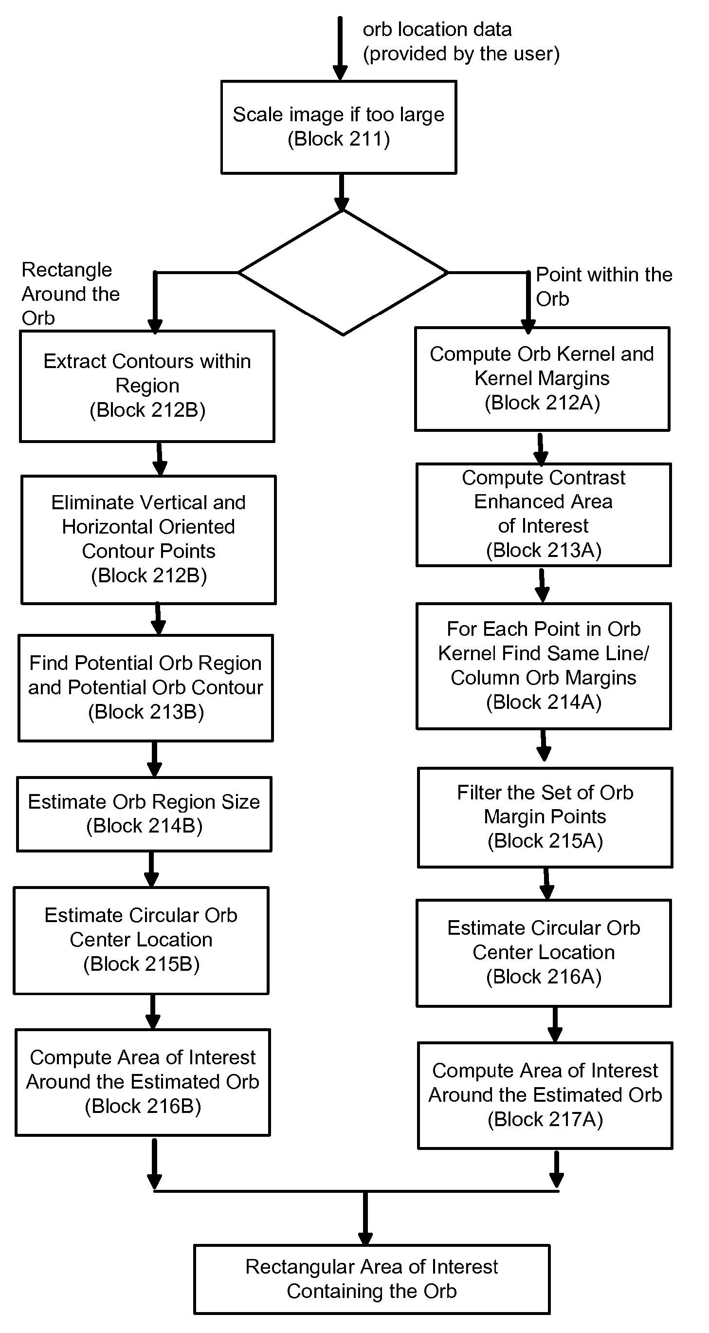
[0134] The orb detection algorithm can be decomposed into two parts, as illustrated in the flow diagram of FIG. 39. Block 21 that computes an rectangular area of interest containing the orb pointed by the user and Block 22 that computes the actual orb location. The input data used by the detection algorithm is the data provided by the user (as output of Block 1) and the luminance (gray scale) component of the original color image that is to be processed.

[0135] The final orb detection data consists of a rectangular area of interest, that encompasses the orb with a predefined 50 pixel border (if the orb is located at least 50 pixels from the corresponding image margin, otherwise, the border equals the distance to the corresponding image margin) and a binary mask (within the area of interest), exactly covering the orb.

Detecting Area of Interest Containing an Orb

[0136] Detection of an area of interest containing an orb may be performed according to the flow diagram of FIG. 40. Block ...


PUM


Abstract

Flash image orb artifacts arising from specular reflections from airborne particles are corrected. A specific location is detected within a digital image of a flash image airborne particle artifact (orb). A defined curved plane shape is electronically identified within the image. Luminances are analyzed of pixels within the identified shape to assess whether the shape in fact corresponds to an orb. The digital image is corrected by removing the orb. One or more pixel values are adjusted inside the orb, and one or more edge pixel values of the orb are also adjusted.

Description

PRIORITY [0001] This patent application claims the benefit of priority to U.S. provisional patent application No. 60 / 821,956, filed Aug. 9, 2006, which is incorporated by reference. RELATED APPLICATION [0002] This application is related to a contemporaneously-filed patent application by the same assignee entitled “DETECTION OF AIRBORNE FLASH ARTIFACTS USING PREFLASH IMAGE”.BACKGROUND OF THE INVENTION [0003] 1. Field of Invention [0004] The invention relates to detection and correction of digital image artifacts that appear in images acquired particularly by compact digital still cameras due to flash reflections from airborne particles such as dust and water vapor (or small waterborne particles in underwater photography) that are placed out of focus. [0005] 2. Description of the Related Art [0006] While working with camera companies, there is a constant complaint about “orbs” which are unwanted (or for some wanted) artifacts in flash images due to specular reflections from airborne (...

Claims


Application Information

Patent Timeline
Patent Type & Authority Applications(United States)
IPC IPC(8): G06K9/40G06V10/30G06V10/48
CPCG06K9/40G06K9/4633G06T5/40G06T2207/20148G06T5/002G06T5/008G06T2207/20032G06T7/0081G06T7/11G06T7/136G06V10/30G06V10/48G06T5/94G06T5/70
Inventor DAVID, EMILIANVERTAN, CONSTANTINZAMFIR, ADRIANDRIMBAREAN, ALEXANDRUCORCORAN, PETERSTEINBERG, ERAN
Owner FOTONATION LTD
Learn More