Method and apparatus for editing timing diagram, and computer product

a timing diagram and timing technology, applied in the field of logic verification of hardware modules, can solve the problems of prolonged design period and very difficult design work for users

Active Publication Date: 2008-03-27
FUJITSU LTD
View PDF14 Cites 4 Cited by
  • Summary
  • Abstract
  • Description
  • Claims
  • Application Information

AI Technical Summary

Benefits of technology

[0009]It is an object of the present invention to at le...

Problems solved by technology

This led to a problem that a design work is very difficult for ...

Method used


Image

  • Method and apparatus for editing timing diagram, and computer product
  • Method and apparatus for editing timing diagram, and computer product
  • Method and apparatus for editing timing diagram, and computer product

Examples


Embodiment Construction

[0029]Exemplary embodiment of the present invention will be explained in detail with reference to accompanying drawings.

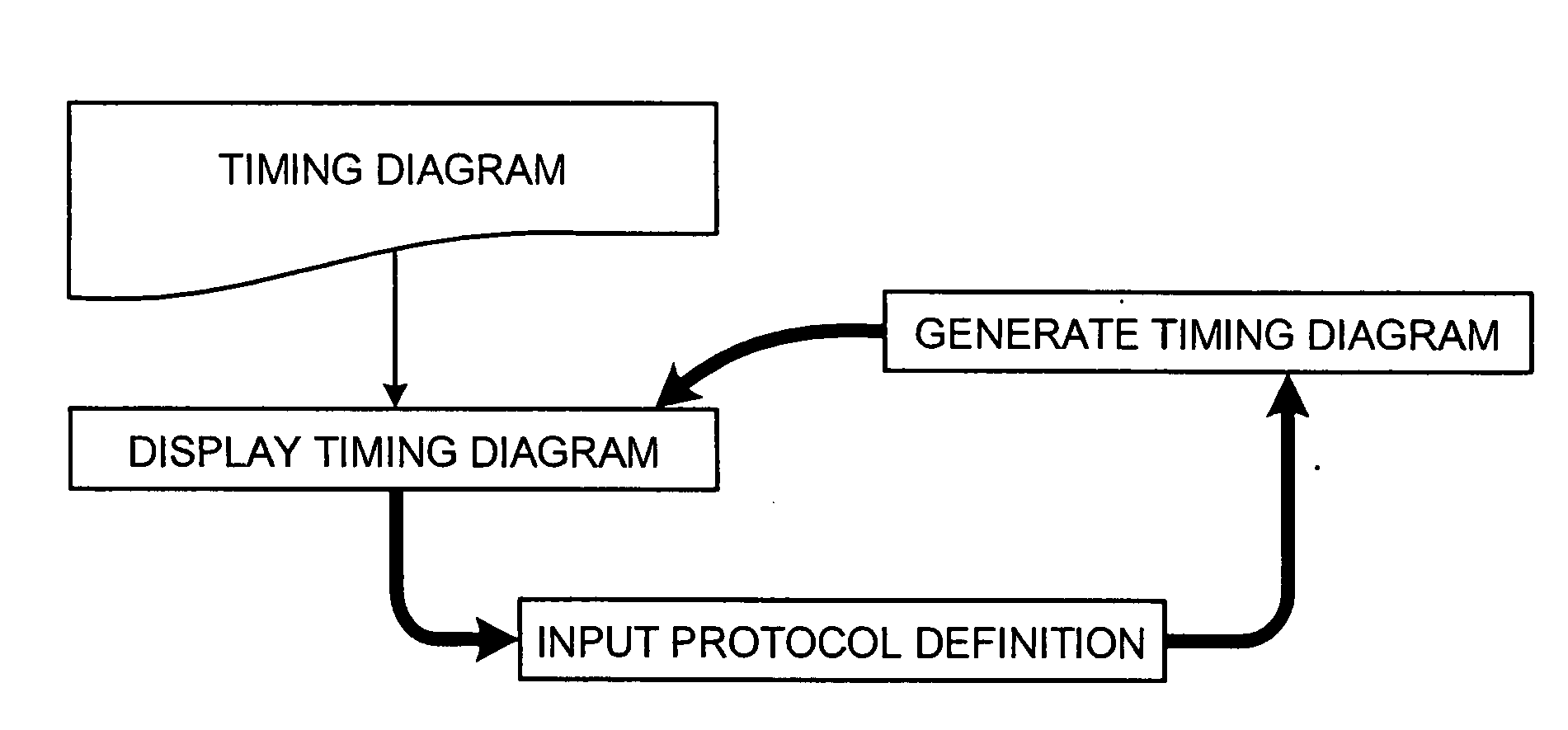
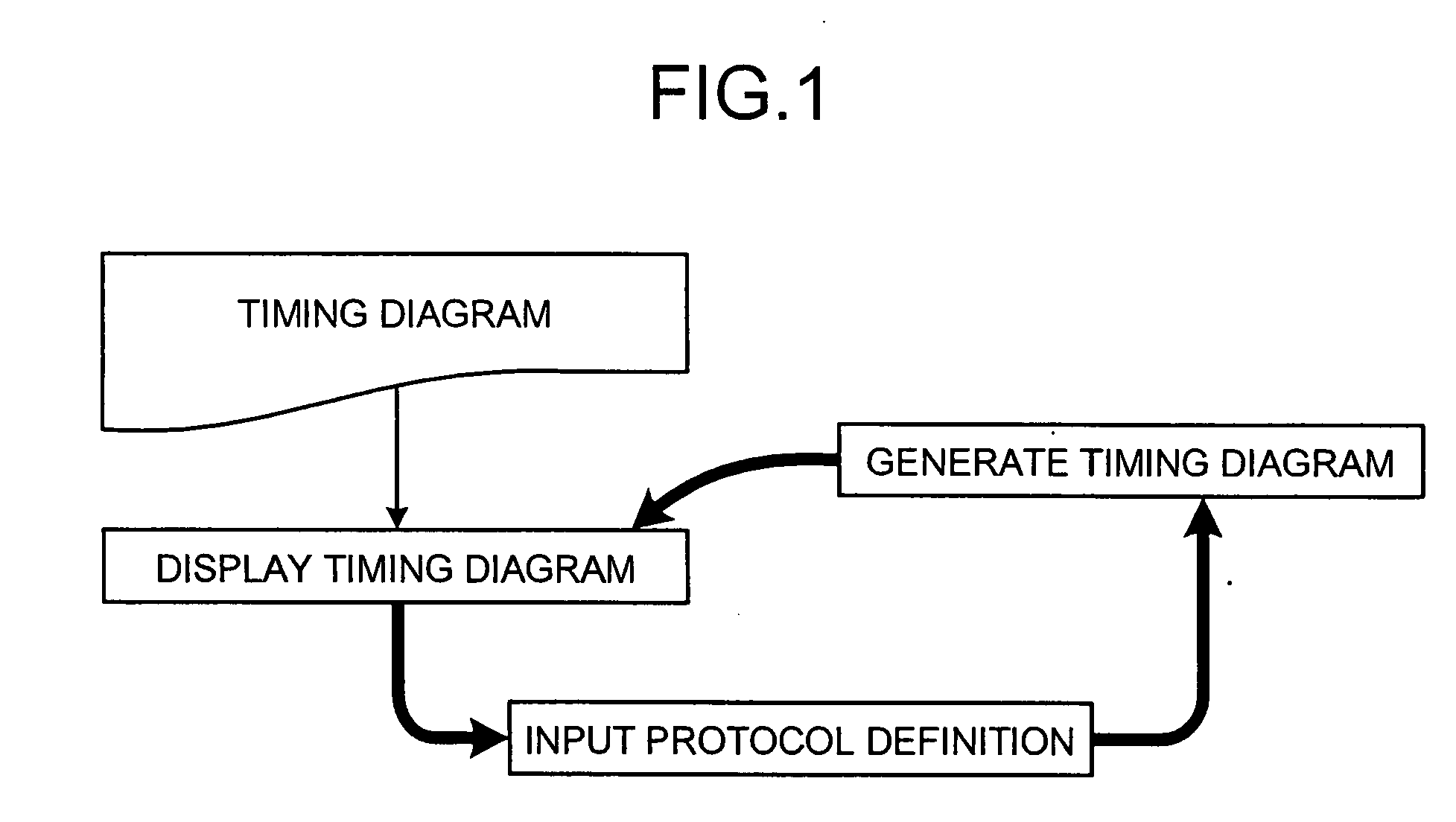
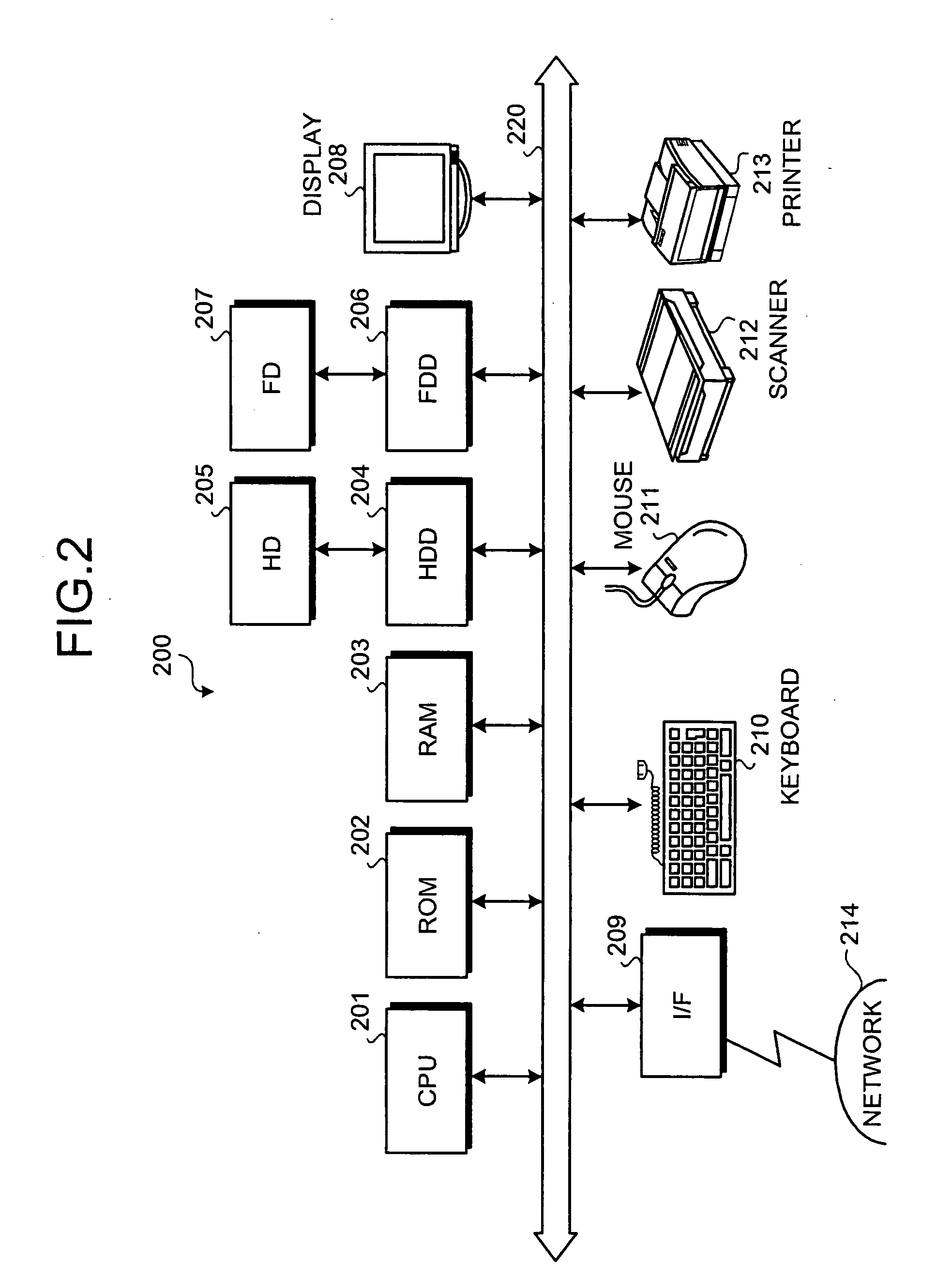
[0030]FIG. 1 is a schematic for explaining timing diagram editing processing according to embodiments of the present invention. The timing diagram editing processing shown in FIG. 1 is the processing to be executed in preparing an interface protocol regarding a hardware module. Firstly, a timing diagram is displayed on a GUI of a timing diagram editing apparatus 200 (see FIG. 2).

[0031]For example, it may be arranged such that the timing diagram is automatically drawn on the GUI from data input in a table format or a text format. It may also be so arranged that the timing diagram is prepared by directly editing on the GUI by a user.

[0032]The timing diagram is a diagram expressing in a time sequence the processing to be executed in an object to be designed and is an example of the sequence satisfying the interface protocol of the hardware module. Detailed description...


PUM


Abstract

A timing diagram is displayed on GUI of a timing diagram editing apparatus. Numerical information indicating the repetition number for which a waveform image within the arbitrary number of clocks is repeated is received, and the repetition number is determined based on the numerical information. A sequence image is displayed on GUI by replaying the waveform image with a continuous waveform image that is formed by repeating the waveform image for the determined repetition number of times.

Description

CROSS-REFERENCE TO RELATED APPLICATIONS[0001]This application is based upon and claims the benefit of priority from the prior Japanese Patent Application No. 2006-260338, filed on Sep. 26, 2006, the entire contents of which are incorporated herein by reference.BACKGROUND OF THE INVENTION[0002]1. Field of the Invention[0003]The present invention relates to a technology of a timing diagram editing in logic verification of a hardware module, and more particularly, to a technology of mathematically describing an interface protocol of a hardware module.[0004]2. Description of the Related Art[0005]Usually, in specifications regarding a hardware module, an interface protocol is described by combining an overall description mainly in natural language and an illustration of typical examples by a timing diagram. A general-use word processor and a timing diagram editing tool are used for preparation of such kind of specification.[0006]Recently, technologies are provided for automatically gener...

Claims


Application Information

Patent Timeline
IPC IPC(8): G06F11/36
CPCG06F17/5031G06F30/3312
Inventor IWASHITA, HIROAKI
Owner FUJITSU LTD
Why Eureka
Try Eureka