Drive system of synchronized electric motor

A synchronous motor and drive system technology, applied in AC motor control, electronic commutation motor control, control system and other directions, can solve the problems of low sensitivity and submerged position information in noise, etc.

Inactive Publication Date: 2013-05-01
HITACHI AUTOMOTIVE SYST LTD +1
View PDF6 Cites 3 Cited by
  • Summary
  • Abstract
  • Description
  • Claims
  • Application Information

AI Technical Summary

Problems solved by technology

At present, most of the sensorless control that has been put into practical use is based on the induced voltage (speed voltage) generated by the PM motor. Therefore, the sensitivity is low in the stop and low speed range of small induced voltage, and the position information will be submerged in the in the noise

Method used


Image

  • Drive system of synchronized electric motor
  • Drive system of synchronized electric motor
  • Drive system of synchronized electric motor

Examples


Embodiment Construction

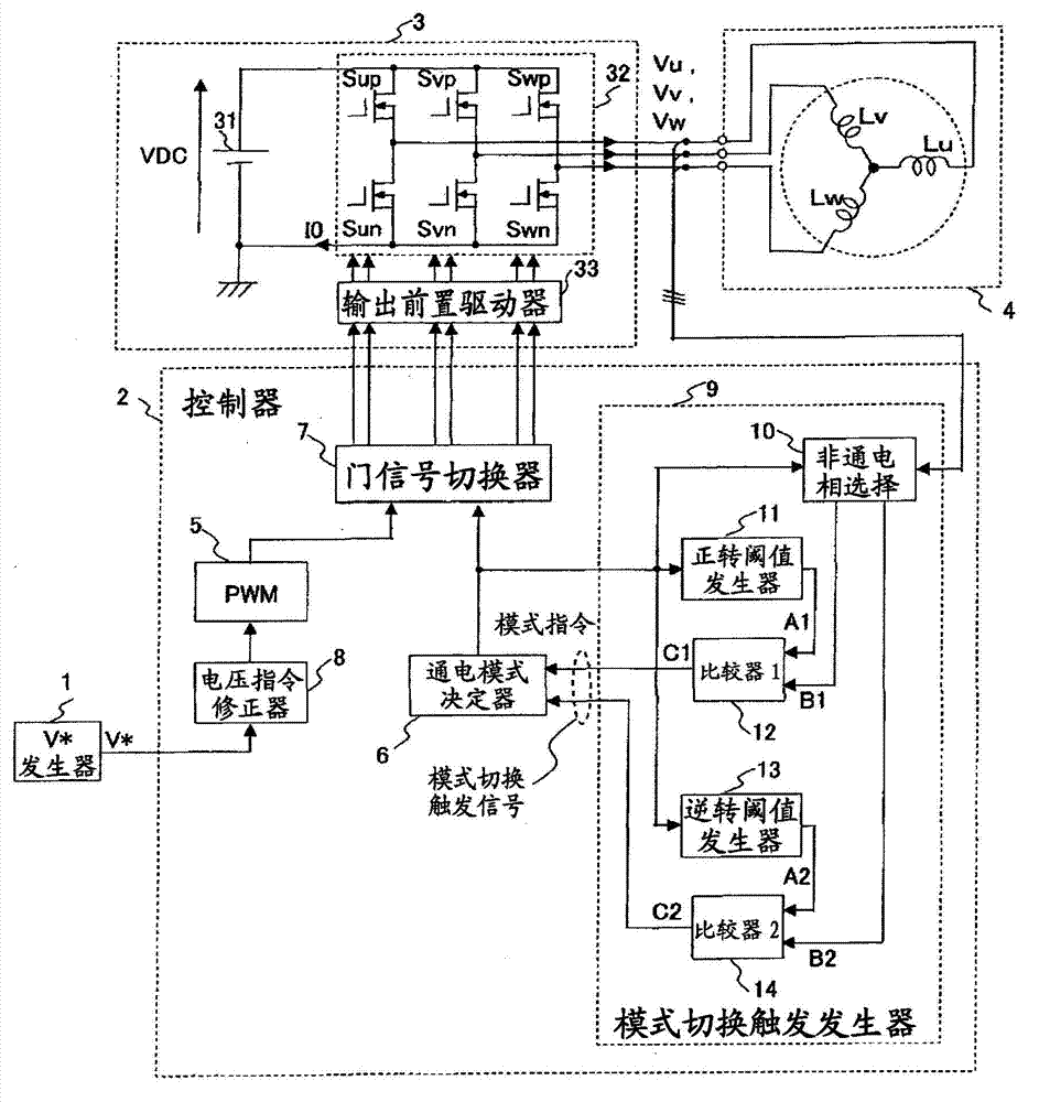
[0049] Below, use Figure 1 to Figure 23 , the configuration and operation of a drive system for a synchronous motor according to an embodiment of the present invention will be described.

[0050] First, use figure 1 The overall configuration of the drive system of the synchronous motor according to the present embodiment will be described.

[0051] figure 1 It is a block diagram showing the overall configuration of a drive system for a synchronous motor according to an embodiment of the present invention.

[0052] The synchronous motor drive system of this embodiment includes a voltage command generator (V* generator) 1 , a controller 2 , an inverter 3 , and a synchronous motor (PM motor) 4 .

[0053] The PM motor 4 is a three-phase synchronous motor holding a plurality of permanent magnets on the rotor.

[0054] The V* generator 1 is a controller positioned upstream of the controller 2 that generates a voltage command V* to be applied to the PM motor 4 . For example, in...


PUM


Abstract

Provided is a drive system of a synchronized electric motor that is capable of driving at speeds near zero. An electricity supply mode determination apparatus (9) detects either an electricity non-supply phase terminal potential of a three-phase synchronized electric motor (4) or a stator coil connection point potential (neutral point potential) of the three-phase synchronized transmitter, and sequentially switches among six electricity supply modes on the basis of the detected value of the potential. In order to supply repeating waveforms of three types of voltage to the synchronized electric motor, said three types of voltage being a positive polarity pulse voltage that causes the synchronized electric motor to generate a positive rotation torque, an inverse pulse voltage that causes the synchronized electric motor to generate an inverse rotation torque, and a zero voltage, as line voltage waveforms of electricity supply phase in each of the six electricity supply modes, a voltage instruction compensator apparatus (8) uses a degree of compensation deltaV to compensate for a voltage instruction that is applied to the synchronized electric motor. The electricity supply phase line voltage is applied to the synchronized electric motor.

Description

technical field [0001] The present invention relates to a drive system for a synchronous motor, and more particularly to a drive system for a synchronous motor suitable for use in estimating the magnetic pole position of a rotor in a sensorless manner and controlling the synchronous motor. Background technique [0002] In the fields of home appliances, industry, and automobiles, for example, motor drives are used for rotational speed control of fans, pumps, compressors, conveyors, elevators, etc., as well as torque assist equipment and positioning control. Among motor drives in these fields, small and highly efficient permanent magnet motors (synchronous motors) are widely used. However, when driving a permanent magnet motor (hereafter referred to as "PM motor"), information on the magnetic pole position of the motor rotor is required, and position sensors such as resolvers and Hall ICs are necessary for this purpose. In recent years, "sensorless control" in which the rotat...

Claims


Application Information

Patent Timeline
Patent Type & Authority Applications(China)
IPC IPC(8): H02P6/18H02P6/06H02P6/08H02P6/182
CPCH02P6/18H02P6/002H02P6/14H02P27/08H02P21/04H02P6/20H02P23/03H02P6/28
Inventor 岩路善尚青柳滋久户张和明高畑良一
Owner HITACHI AUTOMOTIVE SYST LTD
Why Eureka
Try Eureka