Repetitive waveform generator recirculating delay line

a waveform generator and delay line technology, applied in the field of repetition waveform generators, can solve the problems of not being identical and excessively noisy in repetition waveforms

Inactive Publication Date: 2006-08-15
RAYTHEON CO
View PDF8 Cites 2 Cited by
  • Summary
  • Abstract
  • Description
  • Claims
  • Application Information

AI Technical Summary

Problems solved by technology

However, errors can be introduced each time the basic waveform is generated and thus the repeating waveforms might contain excessive noise and not be identical.

Method used


Image

  • Repetitive waveform generator recirculating delay line
  • Repetitive waveform generator recirculating delay line
  • Repetitive waveform generator recirculating delay line

Examples


Embodiment Construction

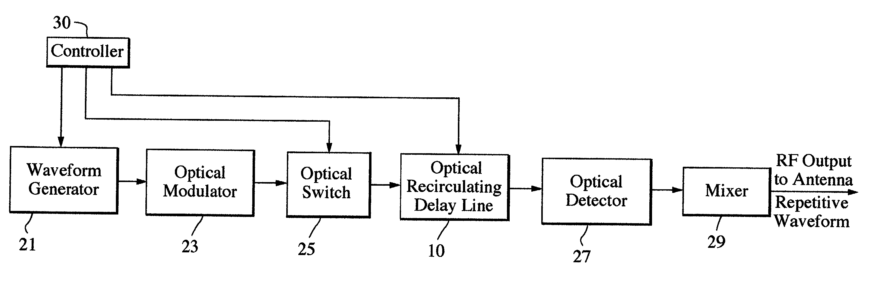
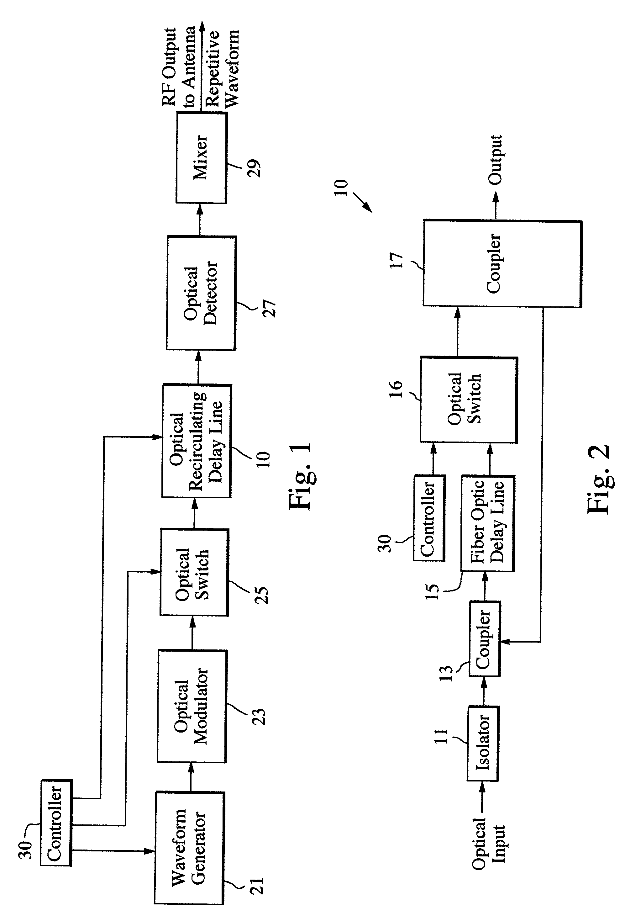
[0012]FIG. 1 is a schematic block diagram of a repetitive waveform generator that includes an RF waveform generator 21 whose output is provided to an optical modulator 23 that provides an RF modulated optical signal to an optical switch 25. The output of the optical switch 25 comprises a basic waveform of limited duration that is intended to be repeated and is provided as an input to an optical recirculating delay line 10. The output of the recirculating delay line comprises repetitions of the basic waveform signal and is provided to an optical detector 27 that detects the RF modulation on the output of the optical recirculating delay line 10. The electrical RF output of the optical detector 27 can be appropriately converted by a mixer 29 to obtain a desired RF signal frequency that can be provided to an antenna, for example. A controller 30 controls the operation of the waveform generator, the optical switch 25 and the optical recirculating delay line 10.

[0013]The RF modulated opti...


PUM

PropertyMeasurementUnit
frequencyaaaaaaaaaa
optical delayaaaaaaaaaa
timeaaaaaaaaaa

Abstract

A recirculating delay line that includes an optical delay circuit generates repetitions of an input signal waveform that is of limited time duration.

Description

TECHNICAL FIELD OF THE DISCLOSURE[0001]This invention relates to repetitive waveform generators that can be employed in RF applications such as radar.BACKGROUND OF THE DISCLOSURE[0002]Advanced radar systems have significantly larger bandwidths and operate over a wide RF range, e.g., up to about 100 GHz in some applications. These advanced radar systems will need to generate ultra fast repetitive intrapulse frequency modulated waveforms.[0003]A known technique of generating ultra fast repetitive intrapulse frequency modulated waveforms is to actually generate the basic waveform for each time it is repeated. However, errors can be introduced each time the basic waveform is generated and thus the repeating waveforms might contain excessive noise and not be identical.[0004]There is accordingly a need for a repetitive waveform generator that generates substantially identical repeating waveforms.SUMMARY OF THE DISCLOSURE[0005]The disclosed invention generates substantially identical repet...

Claims


Application Information

Patent Timeline
Patent Type & Authority Patents(United States)
IPC IPC(8): G02B6/26G02F2/02G01S7/282G02B6/28H01Q3/26
CPCG01S7/282H01Q3/2682H01Q3/2676G02B6/2861
Inventor ROSEN, ROBERT A.KRIKORIAN, KAPRIEL V.NEWBERG, IRWIN L.
Owner RAYTHEON CO
Why Eureka
Try Eureka