
Systems and methods for performing synthetic aperture radar imaging using superchirps

a radar imaging and synthetic aperture technology, applied in the direction of reradiation, instruments, measurement devices, etc., can solve the problems of ambiguity in the range (cross-track) and inability to achieve the full range of the radar, and the doppler bandwidth will be under-resolved, and the azimuth (along-track) aliasing and ambiguity is not easy to solv

Active Publication Date: 2020-02-04
PLANET LABS PBC
View PDF24 Cites 2 Cited by
  • Summary
  • Abstract
  • Description
  • Claims
  • Application Information

AI Technical Summary

Benefits of technology

The patent describes a synthetic aperture radar (SAR) imaging system that uses repeated waveforms to generate imaging data. The system includes a transmitter that transmits superchirps generated by convolving a kernel with a pseudonoise modulated impulse sequence, a receiver that receives the backscatters of the transmitted superchirps and digitizes them, and signal processing circuitry that performs matched filtering on the digitized backscatters. The system can also transmit superchirps of different durations and perform rolling channel separation and squint processing on the digitized backscats. The technical effects of this system include improved imaging resolution and improved signal-to-noise ratios.

Problems solved by technology

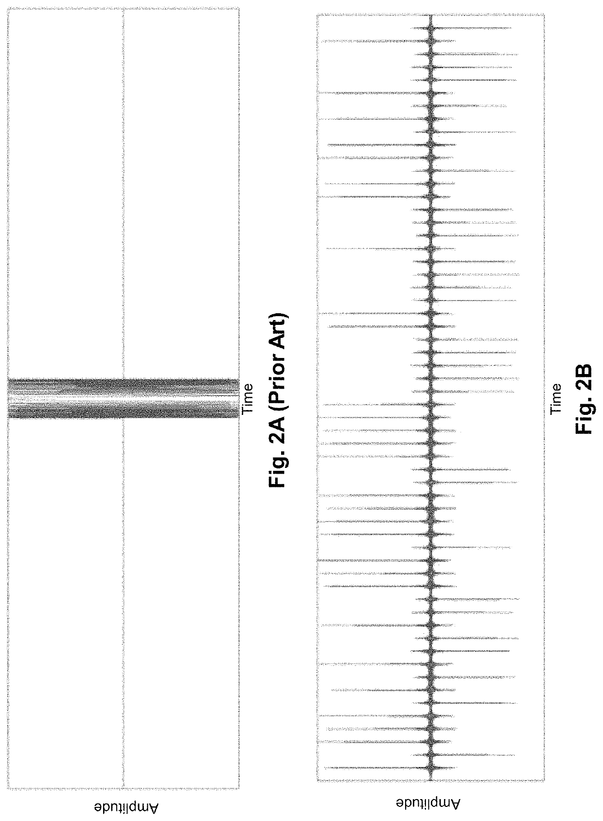
On one hand, if the pulses are transmitted too frequently, then reflections from more than one range will arrive at the receiver simultaneously, leading to range (cross-track) ambiguity.
On the other, if pulses are not transmitted frequently enough, then the Doppler bandwidth will be under-resolved, leading to azimuth (along-track) aliasing and ambiguity.
The decrease in resolution can be offset by operating in spotlight mode with a consequent loss of collection area rate.
Often, the resulting physical antenna is longer than signal-to-noise considerations alone would otherwise require.
The requirement of a large antenna, coupled with typically tight antenna RF precision requirements, typically means that either an expensive rocket with a large payload fairing is required, or a large, high-precision structure must be unfurled in space, raising engineering and manufacturing costs and mission risk.

Method used


Image

  • Systems and methods for performing synthetic aperture radar imaging using superchirps
  • Systems and methods for performing synthetic aperture radar imaging using superchirps
  • Systems and methods for performing synthetic aperture radar imaging using superchirps

Examples


Embodiment Construction

[0037]Turning now to the drawings, synthetic aperture radar (SAR) imaging systems that transmit repeated waveforms based upon pseudonoise sequences in accordance with various embodiments of the invention are illustrated. The waveforms generated by convolving pseudonoise sequences with any of a variety of kernels can be referred to as superchirps. A benefit of superchirps is that backscattered superchirp reflections are amenable to channelized matched filtering, which means that the sampled received signal can be separated into a sufficient number of channels so that a channelized pulse repetition rate can be achieved that is higher than the transmitted pulse repetition rate. In this way, the use of superchirps enables the construction of a transmitter that can avoid aliasing at pulse repetition rates that are below the Nyquist rate.

[0038]In addition to performance gains through channelized matched filtering, SAR systems that utilize superchirps can achieve transmitter and receiver i...


PUM


Abstract

Synthetic aperture radar (SAR) imaging systems that transmit repeated waveforms based upon pseudonoise sequences to generate SAR imaging data in accordance with various embodiments of the invention are disclosed. A synthetic aperture radar in accordance with one embodiment of the invention includes: a transmitter configured to transmit superchirps, where the superchirp is generated by convolving a kernel with a pseudonoise modulated impulse sequence having a flat power spectrum; a receiver configured to receive backscatters of transmitted superchirps and digitize the received backscatters; and signal processing circuitry configured to perform matched filtering on digitized backscatters.

Description

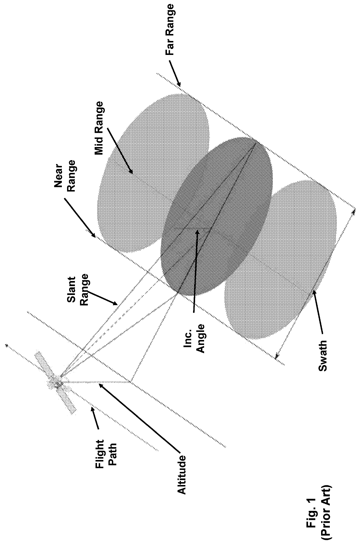
CROSS-REFERENCE TO RELATED APPLICATIONS[0001]The current application claims priority under 35 U.S.C. 119(e) to U.S. Provisional Patent Application Ser. No. 62 / 470,091, entitled “Systems and Methods for Performing Synthetic Aperture Radar Imaging Using Superchirps”, filed Mar. 10, 2017. The disclosure of U.S. Provisional Patent Application Ser. No. 62 / 470,091 is incorporated herein by reference in its entirety.FIELD OF THE INVENTION[0002]The present invention relates generally to synthetic aperture radar systems and more specifically to space based synthetic aperture radar systems.BACKGROUND[0003]The term synthetic aperture radar (SAR) is often used to describe radar systems that use a moving antenna to simulate an extremely large antenna or aperture electronically. SAR systems are often mounted to airborne or space-based platforms and are mounted at an angle relative to the flight path of the platform to which the antenna is mounted. A monostatic SAR utilizes the same platform for t...

Claims


Application Information

Patent Timeline
Patent Type & Authority Patents(United States)
IPC IPC(8): G01S13/90G01S13/00
CPCG01S13/904G01S13/9041G01S13/346G01S13/9052G01S13/9054G01S13/9076G01S13/26
Inventor RUBEL, MICHAELLEVIT, CREONFERRARO, MATTHEW
Owner PLANET LABS PBC
Learn More