Header float arm load compensation

a header and load compensation technology, applied in the field of harvesters, can solve problems such as damage and digging into the ground, and achieve the effect of constant downforce and greater upfor

Active Publication Date: 2008-04-03
DEERE & CO
View PDF18 Cites 100 Cited by
  • Summary
  • Abstract
  • Description
  • Claims
  • Application Information

AI Technical Summary

Benefits of technology

[0011]in accordance with the first aspect of the invention of float arm load compensation system for a header of an agricultural harvester is provided, comprising a header frame; a plurality of header float arms pivotally coupled to the header frame; a cutter bar fixed to forward ends of the plurality of header float arms; at least one conveyor belt supported on the plurality of header float arms and configured to traverse the header perpendicular to the direction of travel of the header, wherein the conveyor belt is further configured to receive crop material cut by the cutter bar; and a plurality of springs, wherein each spring is coupled to an associated header float arm of the plurality of header float arms to exert a force on the associated header float arm compensating for the weight of cut crop material supported by the associated header float arm.
[0012]The springs of the plurality of springs that support float arms closer to the lateral midpoint of the header may be configured to exert a greater upforce on their associated header float arms than other springs of the plurality of springs that support float arms farther from the lateral midpoint of the header. The plurality of springs may be configured to maintain constant the downforce exerted by their associated header float arms against the ground across a width of the header. The load compensation system may further include a control circuit configured to monitor an operational parameter of the agricultural harvester indicative of the load on the at least one conveyor belt. The control circuit may monitor an operational parameter indicative of a load on the rotor of the harvester. The control circuit may be configured to automatically change the forces exerted by the plurality of springs on their associated header float arms in response to changes in the operational parameter. The load compensation system may further include an accumulator containing gas charged hydraulic fluid coupled to the plurality of springs. The load compensation system may further include a valve configured to simultaneously change the force is applied by the plurality of springs by filling and emptying the accumulator. The load compensation system may further include at least first and second accumulators containing hydraulic fluid under pressure, wherein the first accumulator is coupled to a first group of springs of the plurality of springs, and wherein the second accumulator is coupled to a second group of springs of the plurality of springs. The plurality of springs may be mechanical springs. The mechanical springs may be coil springs.

Problems solved by technology

If the cutter bar and / or the front ends of the arms apply too much pressure to the ground they will dig into the ground and be damaged.

Method used


Image

  • Header float arm load compensation
  • Header float arm load compensation
  • Header float arm load compensation

Examples


Embodiment Construction

[0018]An “upforce”, as that term is used herein, refers to a force applied to a header float arm that tends to lift the forward end of the header float arm upward and away from the ground thereby reducing the force of the header float arm against the ground. It does not imply or require that the force itself be directed upward at its point of application to the header float arm. Indeed, depending upon the geometry of the header float arm, the force may be applied to the header float arm in any direction and at any point along the arm.

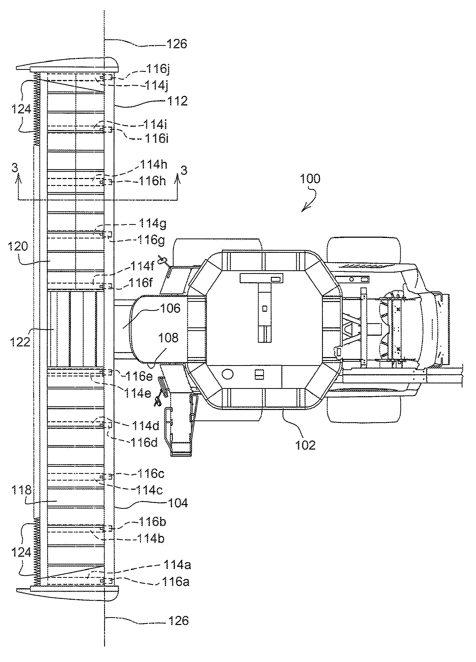
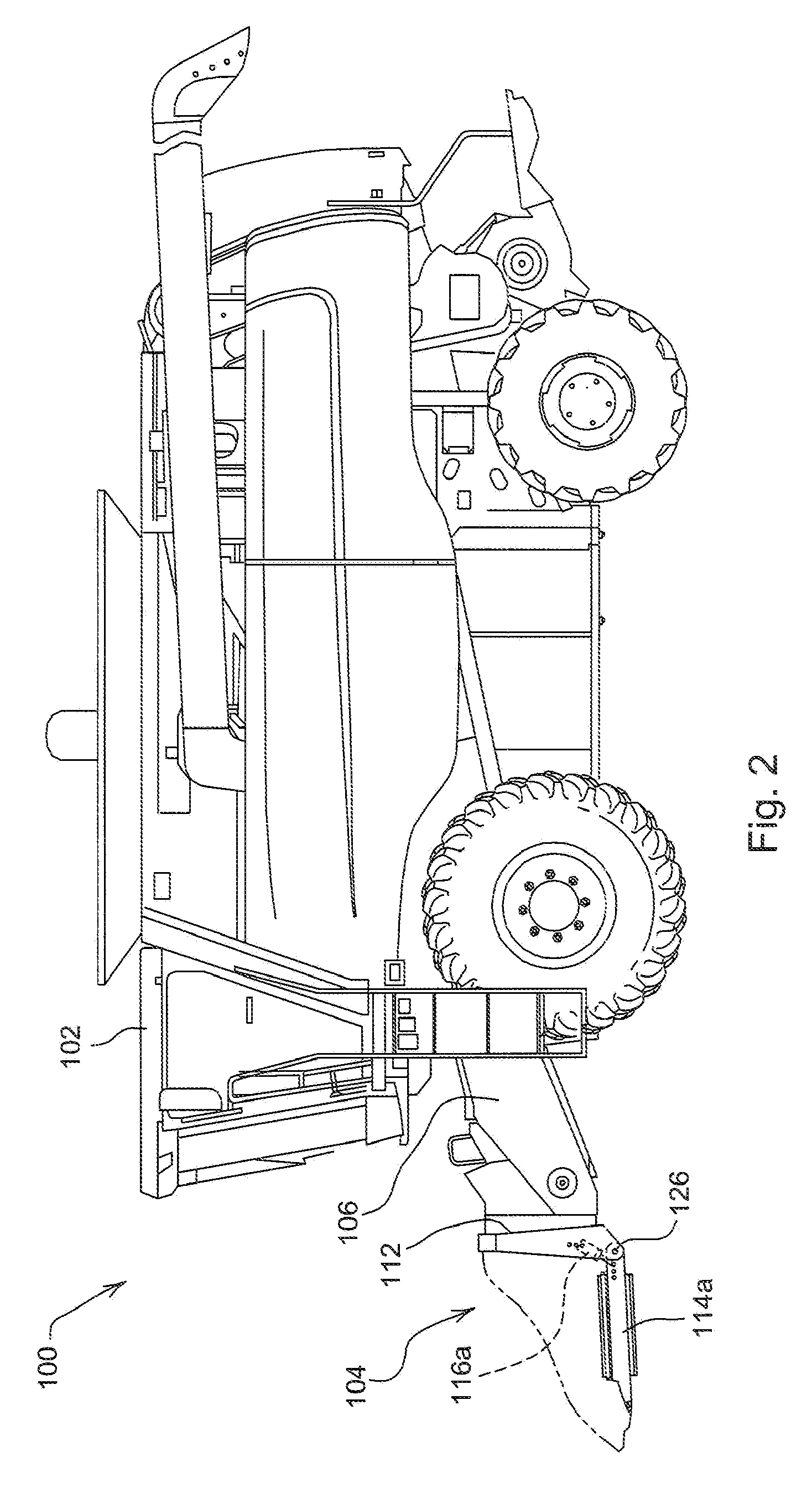
[0019]Referring now to FIGS. 1-2, a combine harvester 100 is illustrated, comprising a vehicle 102 that is wheeled and self-propelled, and also comprising a header 104 which is a Draper platform that is mounted on the front of the vehicle 102.

[0020]Vehicle 102 further comprises a feeder house 106 that is pivotally coupled to the front of chassis 108 of vehicle 102. Header 104 is supported on the front of feeder house 106.

[0021]Header 104 comprises a fra...


PUM


Abstract

A float arm load compensation system for a header of an agricultural harvester includes a header frame; a plurality of header float arms pivotally coupled to the header frame; a cutter bar fixed to forward ends of the plurality of header float arms; at least one conveyor belt supported on the plurality of header float arms and configured to traverse the header perpendicular to the direction of travel of the header, wherein the conveyor belt is further configured to receive crop material cut by the cutter bar; and a plurality of springs, wherein each spring is coupled to an associated header float arm of the plurality of header float arms to exert a force on the associated header float arm compensating for the weight of cut crop material supported by the associated header float arm.

Description

RELATED APPLICATIONS[0001]This invention claims priority to U.S. Prov. Pat. App. Ser. No. 60 / 825,857, attorney docket number 17720, entitled “Header Float Arm Load Compensation”, which was filed on Sep. 15, 2006 by the same inventors.FIELD OF THE INVENTION[0002]This invention relates generally to harvesters. More particularly, it relates to conveying systems for conveying cut crop material to the harvester vehicle.BACKGROUND OF THE INVENTION[0003]Harvesters have headers (typically called “Draper platforms”) that carry cut crop material on conveyor belts. These conveyor belts extend across the width of the header to a central discharge region of the header. The conveyor belts are supported on rollers that, in turn, are mounted on header float arms that are elongated and extend forwardly. These arms are pivotally mounted to a frame of the header. The forward ends of the header float arms are coupled to and support a cutter bar that extends across the width of the header.[0004]The cutt...

Claims


Application Information

Patent Timeline
Patent Type & Authority Applications(United States)
IPC IPC(8): A01D34/00
CPCA01D41/141
Inventor COERS, BRUCE ALANPURYK, CORWIN MARCUSLOVETT, BENJAMIN MAXRAINS, GERALD ERICGRYWACHESKI, SHELDON JOSEPHMELTON, MARK ALAN
Owner DEERE & CO
Why Eureka
Try Eureka