
Motion vector detection apparatus and method

a detection apparatus and motion vector technology, applied in the field of motion vector detection apparatus and method, can solve the problems of high computational complexity of motion vector detection processing necessary for motion compensation, inability to reliably detect motion vectors of small blocks, and inability to accurately detect motion vectors. the effect of low computational complexity and minimum residual cos

Inactive Publication Date: 2008-04-03
KK TOSHIBA
View PDF13 Cites 88 Cited by
  • Summary
  • Abstract
  • Description
  • Claims
  • Application Information

AI Technical Summary

Benefits of technology

The present invention provides an apparatus and methods for efficiently detecting motion vectors in video frames without requiring excessive computing power. This allows for more effective tracking of objects or people across multiple videos.

Problems solved by technology

The technical problem addressed in this patent text is to improve the efficiency and accuracy of motion vector detection in video coding. The current methods require high computational complexity and may result in erroneous motion vector detection. The patent proposes a method to reduce the computational complexity and improve accuracy by using a residual cost threshold and a predicted motion vector obtained from adjacent blocks. However, the effectiveness of this method depends on the complexity of the scene being encoded.

Method used


Image

  • Motion vector detection apparatus and method
  • Motion vector detection apparatus and method
  • Motion vector detection apparatus and method

Examples


Embodiment Construction

[0029]Hereinafter, various embodiments of the present invention will be explained by referring to the drawings. The present invention is not limited to the following embodiments.

[0030](1) Component of Motion Vector Detection Apparatus:

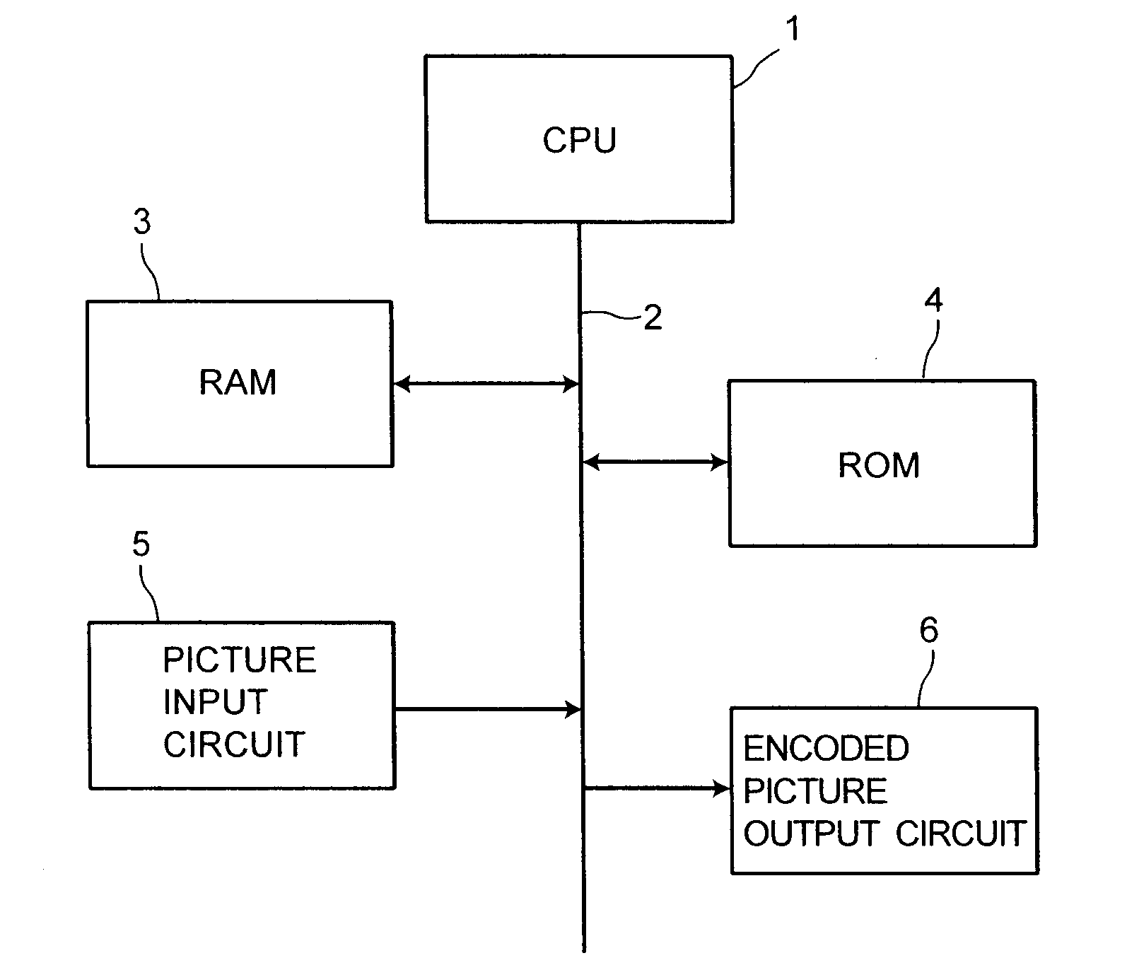
[0031]FIG. 4 is a block diagram of the motion vector detection apparatus according to one embodiment. The motion vector detection apparatus is a von Neumann computer having a picture input / output circuit. In FIG. 4, a bus 2 connects to a CPU 1, a RAM 3, a ROM 4, a picture input circuit 5, and an encoded output circuit 6. The ROM 4 stores a program to detect a motion vector. The CPU 1 reads the program from the ROM 4 in order, and executes motion vector detection.

[0032]A picture is input via the picture input circuit 5, and temporarily stored in the RAM 3. The CPU 1 detects a motion vector from the picture according to the program. After completing motion vector detection, the CPU 1 reads an encoding program from another region of the ROM 4, and encodes...


PUM


Abstract

A plurality of motion vector candidates is extracted, which includes motion vectors of a first set of blocks and a second set of blocks each adjacent to an object block. The first set of blocks has the same size as the object block. The second set of blocks has a smaller size than the object block. A first predicted motion vector of the object block is selected from the plurality of motion vector candidates. A residual cost of each neighboring motion vector is calculated. Each neighboring motion vector points a point within a predetermined range from a point pointed by the first predicted motion vector. A second predicted motion vector having the minimum residual cost is selected from the plurality of neighboring motion vectors. If the first predicted motion vector is equal to the second predicted motion vector, the first predicted motion vector is set as the motion vector of the object block. If the first predicted motion vector is not equal to the second predicted motion vector, a search region pointed by the first predicted motion vector is searched by block matching.

Description


Claims


Application Information

Patent Timeline
Owner KK TOSHIBA
Learn More