Person recognition apparatus and person recognition method

a recognition apparatus and recognition method technology, applied in the field of person recognition apparatus and person recognition method, can solve the problems of difficult to find out an image of a specified person, difficult to stably detect a suspicious-looking person, and inability to cope with the operation of recording an image or issuing an alarm, etc., to achieve efficient access control operation

Inactive Publication Date: 2008-04-03
KK TOSHIBA
View PDF0 Cites 76 Cited by
  • Summary
  • Abstract
  • Description
  • Claims
  • Application Information

AI Technical Summary

Benefits of technology

[0012]An object of the present invention is to provide a person recognition apparatus and person recognition method capable of performing an efficient access control operation with respect to a person or a person monitoring operation.

Problems solved by technology

However, in the system that always records video images captured by the monitor camera, it is not easy to find out an image of a specified person from the video images recorded for a long period of time.
However, in the technique described in Jpn. Pat. Appln. KOKAI Publication No. 2003-169320, it is considered that an ordinary person who does not necessarily hide his face is determined to look like a suspicious person in many cases depending on the setting condition of the cameras and erroneous information will be often issued.
Further, in the technique described in Jpn. Pat. Appln. KOKAI Publication No. 2003-169320, there occurs a problem that it is impossible to cope with the operation of recording an image or issuing an alarm when a suspicious person attempts to prevent his face from being captured by the monitor camera.
However, in Japanese Patent Specification No. 3088880, the person who hides his face is treated as a suspicious person.
Therefore, in the technique disclosed in Japanese Patent Specification No. 3088880, there is a problem that a person whose face does not happen to be directed towards the camera and a person whose face cannot be detected because he wears a pair of sunglasses or mask are all determined to look like a suspicious person.
In the conventional techniques described above, there is a problem that it is difficult to stably detect a suspicious-looking person and perform an efficient authentication process corresponding to the degree of suspicion of each person.

Method used


Image

  • Person recognition apparatus and person recognition method
  • Person recognition apparatus and person recognition method
  • Person recognition apparatus and person recognition method

Examples


first embodiment

[0031]First, the first embodiment is explained below.

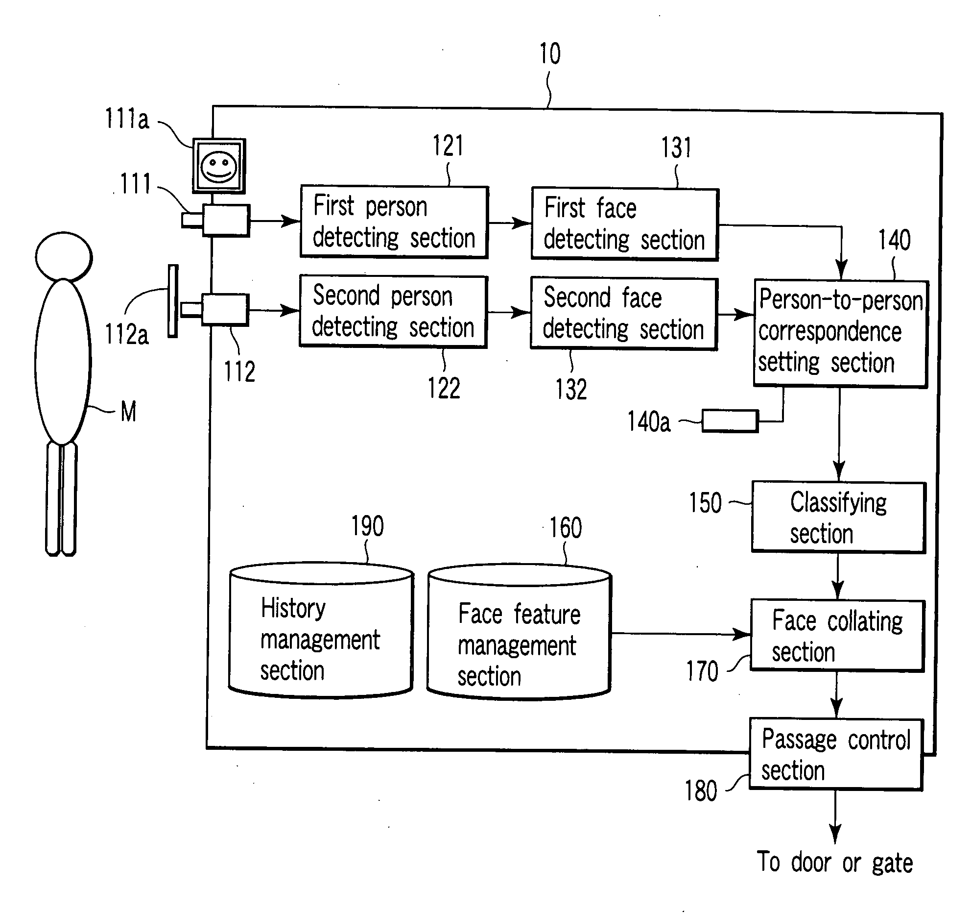
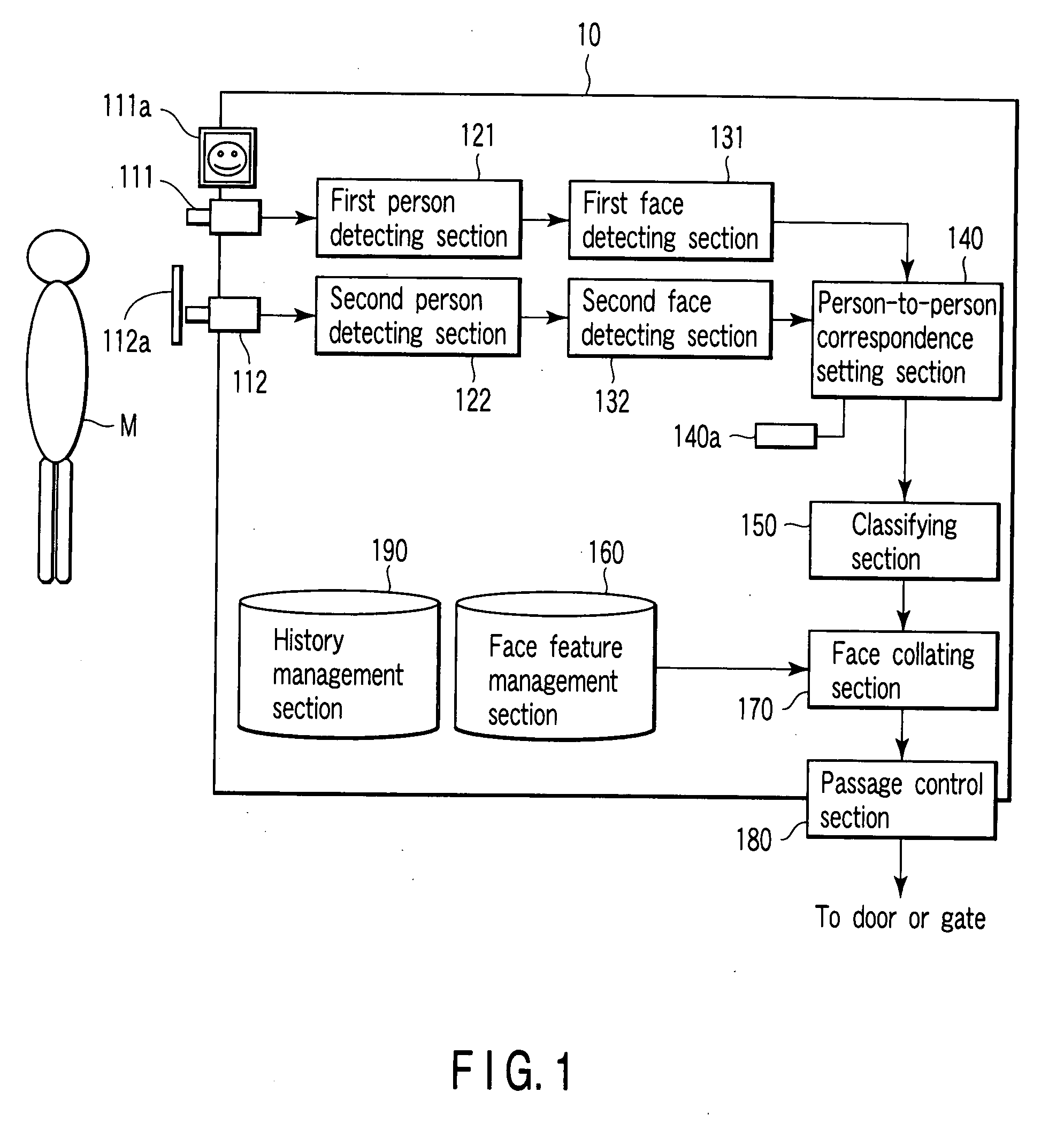
[0032]FIG. 1 schematically shows an example of the configuration of a person (passerby) recognition apparatus 10 as an access control apparatus according to the first embodiment.

[0033]The passerby recognition apparatus 10 shown in FIG. 1 functions as a face collation apparatus that extracts feature information of the face of a person from an image captured by a camera and collates (face collation process) the extracted facial feature information with facial feature information items of registrants. The passerby recognition apparatus 10 shown in FIG. 1 functions as an access control apparatus that permits access (passage in the example shown in FIG. 1) of a person whose facial feature information is determined to coincide with the facial feature information of one of the registrants by the face collation process.

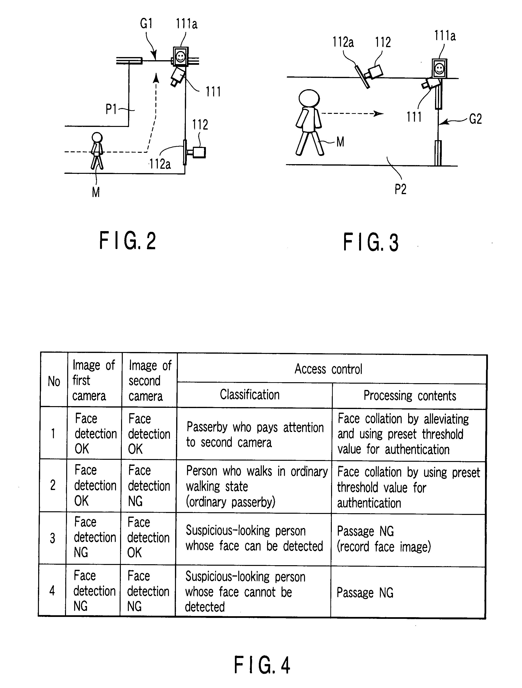
[0034]For example, it is assumed that the passerby recognition apparatus 10 shown in FIG. 1 is applied to an access contr...

second embodiment

[0127]Next, this invention is explained.

[0128]FIG. 6 schematically shows an example of the configuration of a person (passerby) recognition apparatus 20 as an access control apparatus according to the second embodiment.

[0129]The passerby recognition apparatus 20 shown in FIG. 6 functions as the access control apparatus having a face collation function like the passerby recognition apparatus 10 explained in the first embodiment. Further, as the operating condition of the passerby recognition apparatus 20 shown in FIG. 6, the same example applied to the passerby recognition apparatus 10 explained in the first embodiment may be assumed.

[0130]As shown in FIG. 6, the passerby recognition apparatus 20 includes a first image obtaining section 211, second image obtaining section 212, first person detecting section 221, second person detecting section 222, first face detecting section 231, second face detecting section 232, person-to-person correspondence setting section 240, classifying sec...

third embodiment

[0154]Next, this invention is explained.

[0155]FIG. 9 schematically shows an example of the configuration of a person (passerby) recognition apparatus 30 as a person monitoring apparatus according to the third embodiment.

[0156]The passerby recognition apparatus 30 shown in FIG. 9 has a face collating function like the passerby recognition apparatus 10 explained in the first embodiment. In the third embodiment, it is supposed that the passerby recognition apparatus 30 functions as a monitoring apparatus that monitors passersby. For example, the passerby recognition apparatus 30 shown in FIG. 9 is applied to a monitoring apparatus that recognizes the faces of passersby and notifies the recognition results to the external device. In this case, the passerby recognition apparatus 30 can be applied to the access control apparatus of the operating condition explained in the first and second embodiments.

[0157]As shown in FIG. 9, the passerby recognition apparatus 30 includes a first image ob...


PUM


Abstract

A first face detecting section detects the face of a passerby based on an image obtained from a first camera set to be easily recognized by the passerby. A second face detecting section detects the face of the passerby based on an image obtained from a second camera set so that the camera will be difficult to be recognized by the passerby. A classifying section classifies the passerby based on the detection results of the faces by the first and second face detecting sections and adjusts a threshold value for authentication based on the classification result. The face collating section calculates the similarity between the face of the passerby and each of faces of registrants and determines whether the passerby is a registrant or not according to whether the degree of calculated similarity is not lower than the adjusted threshold value for authentication.

Description

CROSS-REFERENCE TO RELATED APPLICATIONS[0001]This application is based upon and claims the benefit of priority from prior Japanese Patent Application No. 2006-265582, filed Sep. 28, 2006, the entire contents of which are incorporated herein by reference.BACKGROUND OF THE INVENTION[0002]1. Field of the Invention[0003]This invention relates to a person recognition apparatus and person recognition method applied to an entrance / exit management system or person monitoring system based on biometric authentication, for example.[0004]2. Description of the Related Art[0005]Conventionally, as the technique used for managing entrance / exit or monitoring a person, the techniques for capturing a walker (passerby), recording the captured image and specifying the walker based on the captured image is proposed. The most popular one of the above techniques is attained by use of a system that always records a video image captured by use of a monitor camera. However, in the system that always records v...

Claims


Application Information

Patent Timeline
Patent Type & Authority Applications(United States)
IPC IPC(8): G06K9/00
CPCG06K9/00288G07C9/00158G06K9/00885G07C9/37G06V40/172G06V40/10
Inventor SUKEGAWA, HIROSHIIRIE, BUNPEI
Owner KK TOSHIBA
Why Eureka
Try Eureka