
Environmental control system

a technology of environmental control and remote controller, which is applied in the direction of electric controllers, ignition automatic control, instruments, etc., can solve the problems of long time lapse, difficult for the operator of such remote controllers to aim a finger, and limited number of conventional hand held remote controllers

Inactive Publication Date: 2007-07-26
HOME COMFORT TECH
View PDF9 Cites 173 Cited by
  • Summary
  • Abstract
  • Description
  • Claims
  • Application Information

AI Technical Summary

Benefits of technology

"The present invention provides a system and method for controlling the operation of appliances in an environment, where the controller can identify the sub-environment in which it is located and control the appliances within that sub-environment. This is achieved by using a remote controller with location recognition means that receives a signal from a beacon or electronic tag attached to the appliance, or from a sensor in the user's device, to identify the appliance. The controller can also communicate with the appliance's identification means to control it. The system includes sub-environments' recognition means that are allocated to each sub-environment and the controller is provided with means for communicating with these recognition means. The system can also include IR-to-RF and RF-to-IR converters to control IR-driven appliances located in different sub-environments. The technical effect of the invention is to enable users to control the operation of appliances in their environment based on their location, making the operation more convenient and efficient."

Problems solved by technology

Many of the conventional hand held remote controllers can control only a limited number of appliances because of the small size of their displays, as well as for other reasons.
Moreover, in some cases it is difficult for the operator of such remote controllers to aim a finger to perform a ‘press action’ on preferred icon / button of a small size.
Commonly, the user has to browse through one or more irrelevant menus before finding the desired appliance, which is very inconvenient particularly if the number of the appliances, and therefore the number of menus, is large.
In such cases, a long time may lapse before the user finally reaches the preferred option, which may be problematic, and sometimes crucial, in cases of emergency situations, for example, when an ambulance service is sought by use of the capability of the remote controller to operate as a telephone device.
In addition, in such cases the number times, which the user of the controller has to press on icons, is large, which is a problem if the user of the controller is a person that has a physical problem that does not allow the user to operate the controller in ‘normal’ manner.
Because of the above drawbacks, some hand held remote controllers are limited to control a small number of appliances, e.g. located in a single room, while other systems, designed to control a large number of appliances in a relatively extended area, are complicated, difficult to operate and learn, and, in addition, they are costly to install.
The known remote controllers of electrical appliances are generally intended for use by healthy people, and therefore, are ill-equipped for satisfying the needs of elderly and handicapped, and disabled persons.
For example, an elderly or physically challenged person may not be capable of depressing buttons, or icons, to select / operate an appliance, or may not be able to see, or at least to see clearly, the iconic representation of appliances and / or the control options.
However, U.S. Pat. No. 5,016,003 has the drawbacks that the menus are not selected automatically according to the actual location of the controller, and, secondly, a user has to wait a considerable amount of time before the desired options are displayed to him.
Both the aforesaid methods comprise a user interface that is relatively complex and not as easy to learn as would be desirable and further require complex and expensive apparatus.
This method too requires a relatively complex user interface and is neither simple nor quick to operate.
Further, the apparatus it requires is relatively complex.
It is seen therefore that none of the remote control systems and Environment Control Systems (ECSs) known in the art is fully satisfactory for operation by physically challenged, or elderly, persons.
It is also seen that none of the remote control systems and Environment Control Systems (ECSs) known in the art is fully satisfactory in terms of irrelevant menus being displayed to the user of these systems.

Method used


Image

  • Environmental control system
  • Environmental control system
  • Environmental control system

Examples


Embodiment Construction

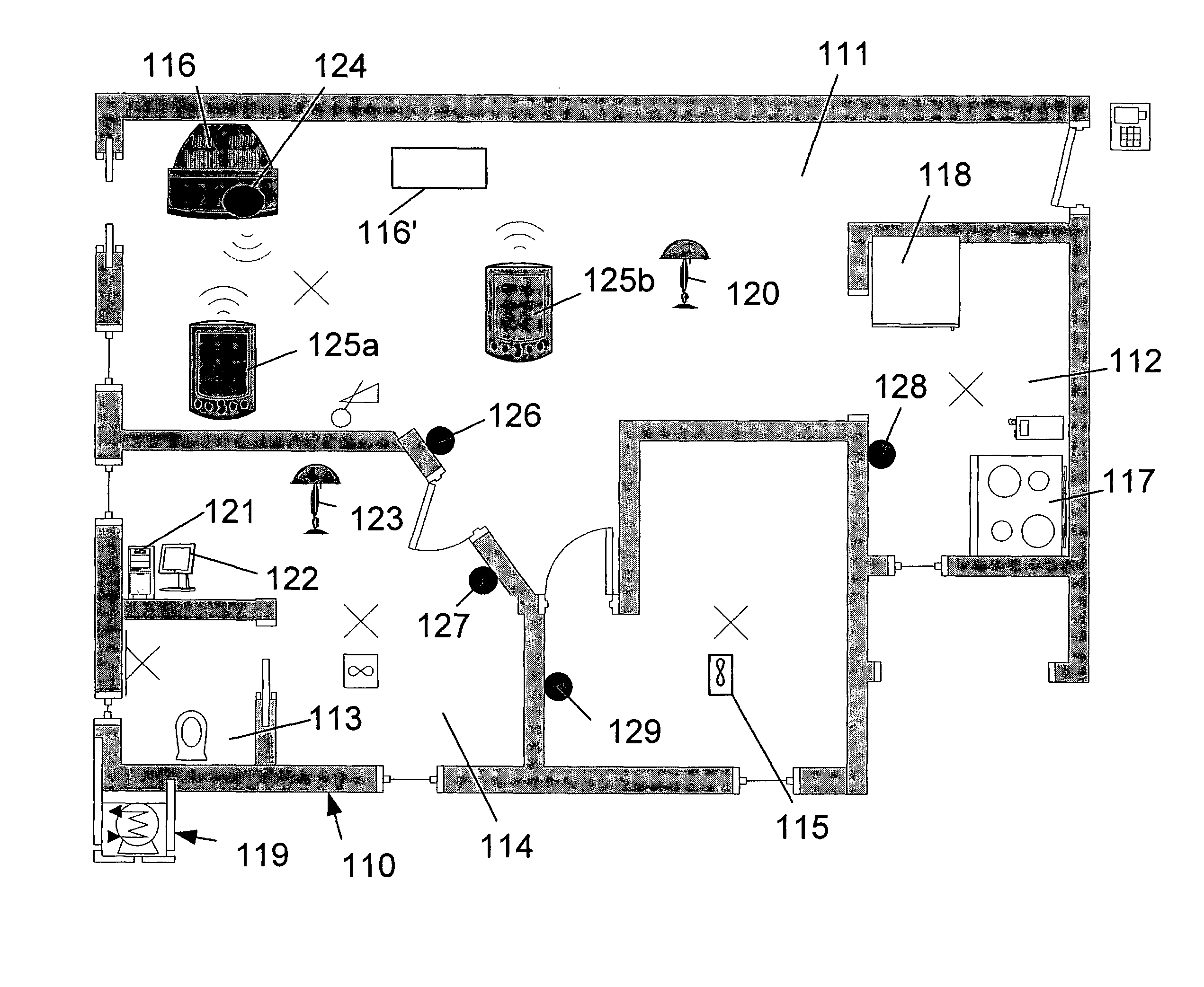
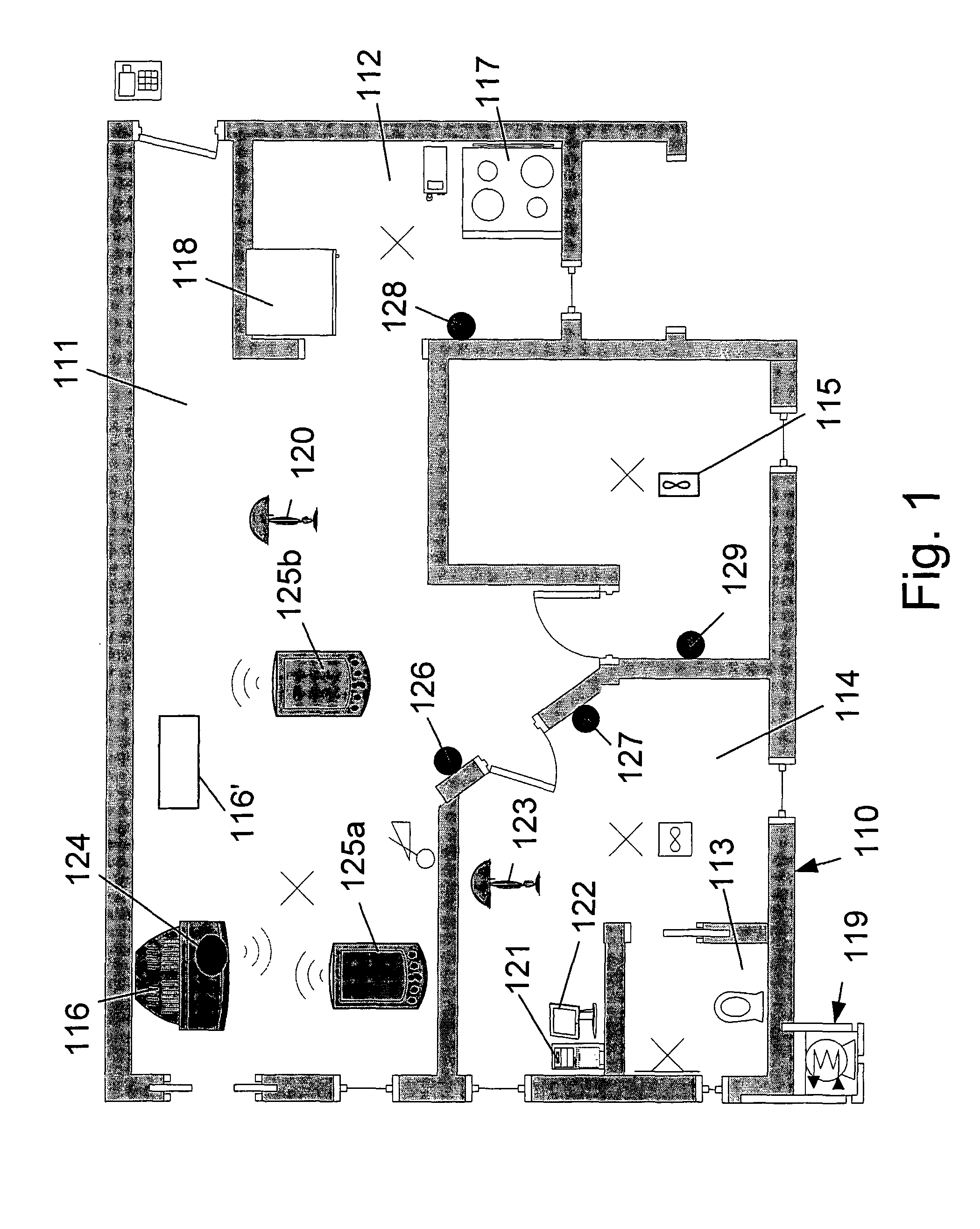
[0088]FIG. 1 schematically illustrates an embodiment of the system of the present invention, wherein the user lives and moves in an exemplary flat illustrated at 110 in schematic plan view. Flat 110, being an exemplary environment includes: living room 111, kitchen 112, toilet room 113 and study room 114. Reference numeral 115 denotes a spare room which is empty at the moment and does not contain controllable appliances.

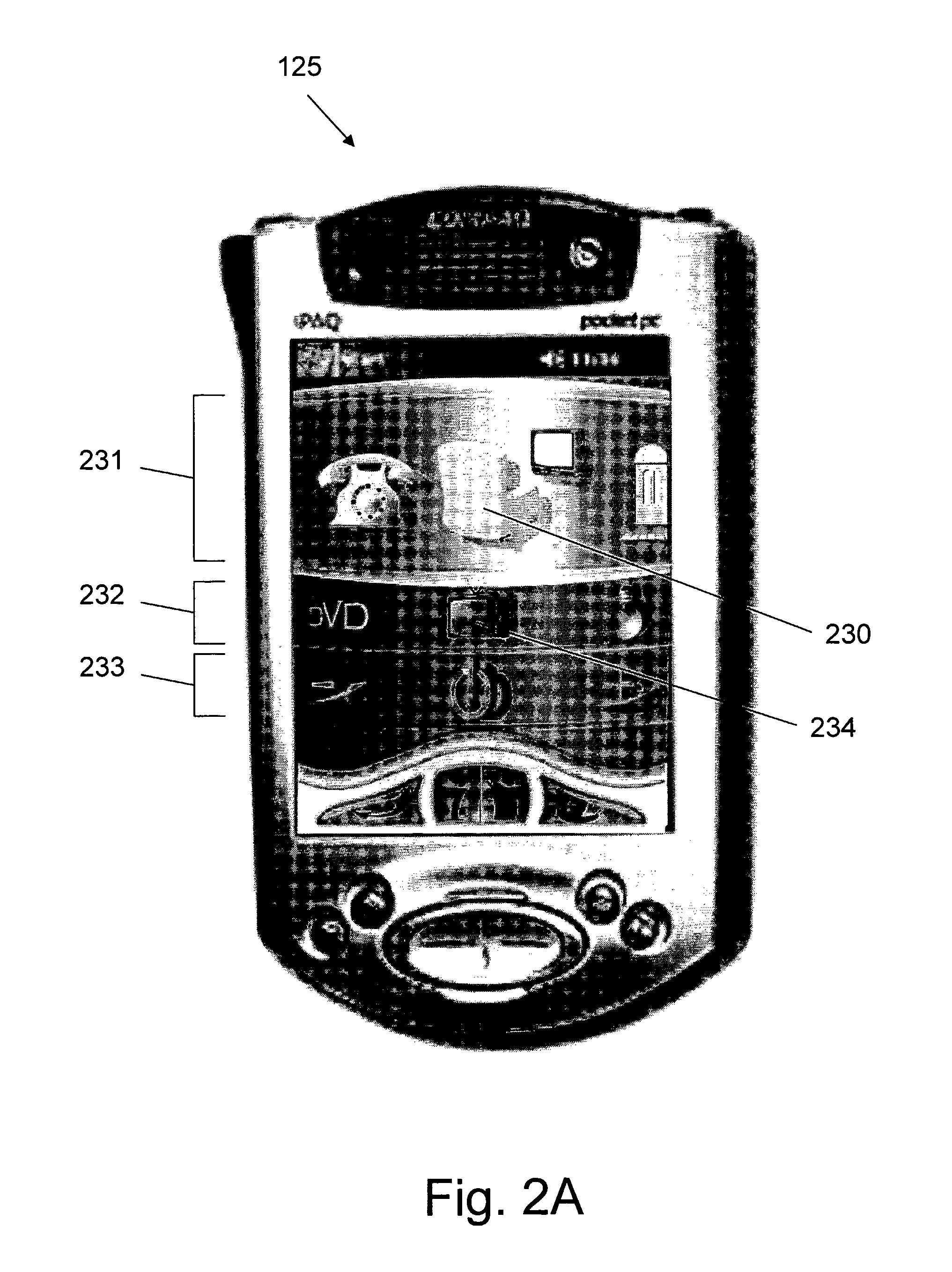
[0089] Living room 111 includes, according to this example, a TV set (116), a DVD (116′) and a lamp 120. Kitchen 112 includes gas stove 117 and dish washing machine 118. Toilet room 113 includes a boiler 119, and study room 114 includes computer 121, computer's monitor 122 and lamp 123. All of the aforesaid appliances are configured to be wirelessly controlled by remote controller 125. Controller 125 is shown in two positions, one position (125a) being directly in front of and close to TV set 116 and the other (125b) being any other position in living room 111.

[009...


PUM


Abstract

System for allowing a user, by use of a remote controller, to control the operation of appliances located in different sub-environments of an environment, that comprises a plurality of sub-environments' recognition means, each one is allocated to a respective sub-environment and equipped with a code unique to the respective sub-environment; and a remote controller, configured to obtain from the recognition means location signal that contains the unique code to recognize the sub-environment the controller is currently in. The controller introduces to the user, in response to the recognition of a sub-environment, control options relevant only to appliances that are located in the recognized sub-environment. The controller includes user interaction means to allow the user to activate the control options, as desired by him.

Description

FIELD OF THE INVENTION [0001] This invention relates to the field of remote controllers of electrical appliances, equipments and communication means, generally known collectively as Environmental Control Systems (ECS). More particularly, the present invention relates to a portable remote controller for controlling the operation of a large number of appliances in a most convenient manner. BACKGROUND OF THE INVENTION [0002] As more and more electrical appliances are added to living and / or working environments, and to other environments, such as a warehouse, a car, backyards, and so forth, it becomes increasingly desirable, and sometimes necessary, to remotely control and program said appliances. [0003] Remote control systems are known for operating appliances, equipment and different types of electrical devices and apparatuses, such as TV, VCR, etc., but they can also operate other devices and applications, such as phones, Internet applications, etc. (hereinafter referred to collectiv...

Claims


Application Information

Patent Timeline
Patent Type & Authority Applications(United States)
IPC IPC(8): G08C19/00G08C17/00H04B1/20H04M1/72415
CPCG08C17/00G08C2201/40H04M2250/06H04M1/72533H04M2250/02H04B1/202H05B47/195H04M1/72415H05B47/1965
Inventor NISENBOIM, GREGORYNISENBOIM, EVGENY
Owner HOME COMFORT TECH
Learn More