Glass door hinge structure

Inactive Publication Date: 2008-04-10
LIN KUN TA INDAL
View PDF4 Cites 15 Cited by
  • Summary
  • Abstract
  • Description
  • Claims
  • Application Information

AI Technical Summary

Benefits of technology

[0007]Therefore, it is a primary objective of the present invention to overcome the shortcomings of the prior art by providing a glass door hinge structure that can be installed on a lateral side of a glass door after the glass door is combined with the hinge body, hinge cover, axial bolt and fixing base, and the fixing base is fixed on the edge of a doorway. The hinge body is a thickened face portion, and the hinge cover has a protrusion attached onto an internal surface of the hinge cover, and the protrusion is in form of an indent, and both sides of the indent respectively have a penetrating hole for installing the axial bolt, and upper and lower positions of the thickened face portion have two transversal screw thread holes, such that the screw thread hole can be penetrated through the inner edge of the penetrating hole for an interconnection. A right-angled concavely cut plane is disposed on upper and lower positions on the same side of the axial bolt, so that after the indent on the hinge body is embedded with the protrusion in the fixing base, the through hole of the protrusion in the fixing base can be aligned precisely with two penetrating holes of the protrusion of the hinge body and a passing hole of the axial bolt, and the long screw bolt outside the hinge body can be screwed into the screw thread hole all the way to the upper limit position of the axial bolt concavely cut plane of the penetrating hole. Finally, the glass door and hinge cover are installed, and the long screw bolt is turned to adjust the angle of the glass door and align the glass door evenly with the doorway. The invention also can enhance the screw connection and application of the long screw bolt and prevent the glass door hinge structure from being damaged easily.
[0008]Another objective of the present invention is to provide a glass door hinge structure, wherein a right-angled concavely cut plane is disposed at upper and lower positions of the same side of the axial bolt and embedded into the fixing base of the hinge body. After the axial bolt is passed through the two holes, the long screw bolt outside the hinge body is screwed into its screw thread hole and onto the concavely cut plane of the of the penetrating hole of the axial bolt, and the whole distal surface of the long screw bolt can be attached completely onto the concavely cut plane of the axial bolt. The long screw bolt is turned inward or outward for adjusting the angle of the glass door and evenly aligning the glass door with the doorway.

Problems solved by technology

However, experienced construction workers at construction sites usually find that if the angle of the foregoing glass door F is adjusted, the screw bolt E is screwed into the screw thread hole A4 adjacent to the penetrating hole A3 in the indent A2 of the hinge body A, and the length of the thread in the screw thread hole A4 is too short, and thus only a very short length is available for the screw connection.
If a construction work is not completed at one time, repeated installations for several times will completely damage the screw thread hole A4, and the angle adjustment cannot be made for the next time.
As a result, a rework is needed, and such time-consuming and laborious construction causes tremendous inconvenience.

Method used


Image

  • Glass door hinge structure
  • Glass door hinge structure
  • Glass door hinge structure

Examples


Embodiment Construction

[0019]The above and other objects, features and advantages of the present invention will become apparent from the following detailed description taken with the accompanying drawing.

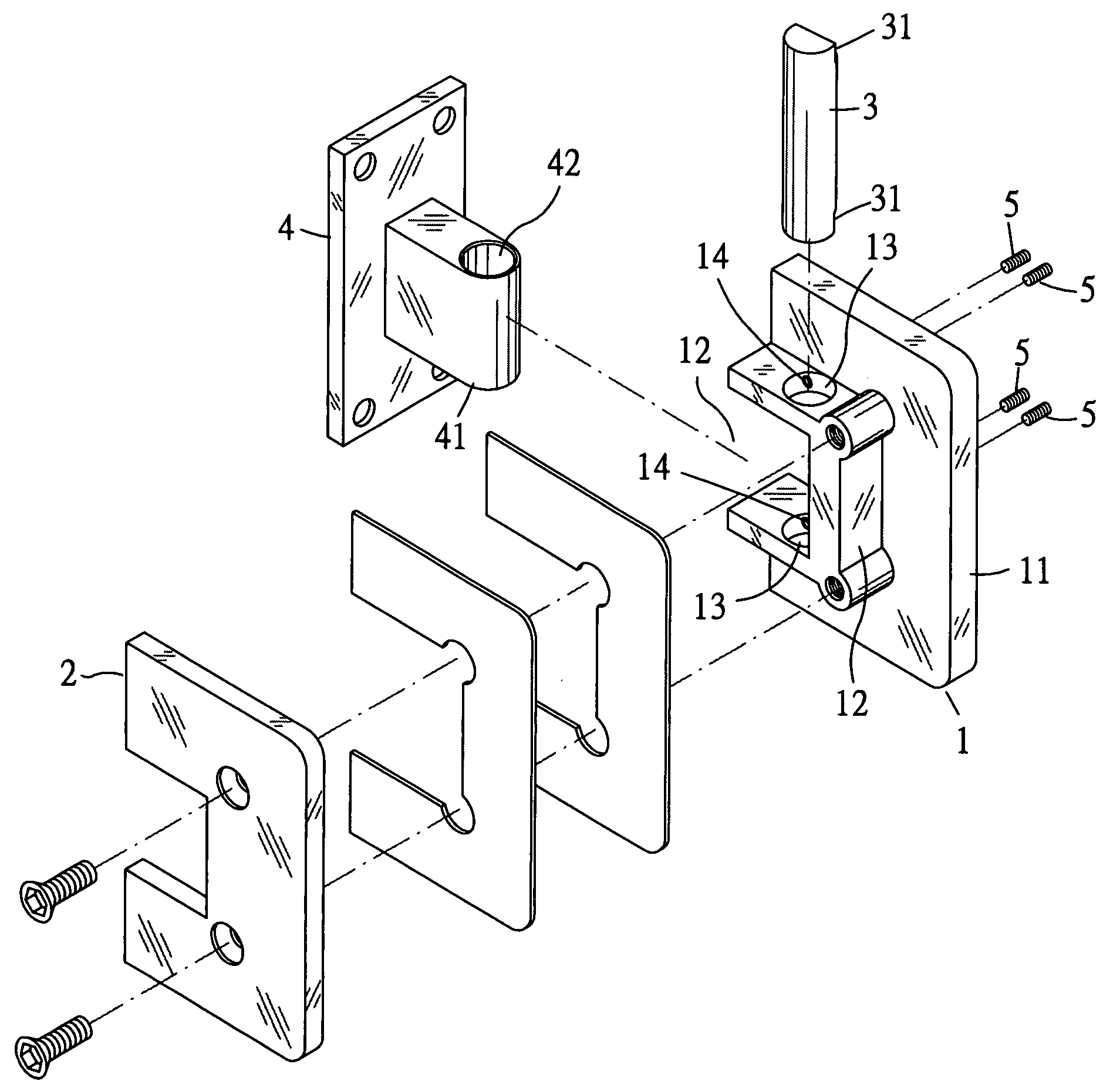
[0020]Referring to FIGS. 3A and 3B for a glass door hinge structure of the present invention, the glass door hinge structure is installed at upper and lower positions of a lateral side of a glass door F, such that the glass door F is combined with the hinge body 1, hinge cover 2, axial bolt 3 and fixing base 4 and the fixing base 4 is fixed onto an edge of a doorway as shown in FIG. 5. The hinge body 1 is a thickened face portion 11, and the hinge cover 2 has a protrusion 12 attached onto the internal surface of the protrusion 12, and the protrusion 12 has an indent 121, and a penetrating hole 13 is disposed separately on both sides of the indent 121 for installing the axial bolt 3. Further, upper and lower positions of the thickened face portion 11 have two parallel transversal screw thread holes 14, so ...


PUM


Abstract

A glass door hinge structure is installed on a lateral side of a glass door, and the glass door is combined with a hinge body, a hinge cover, an axial bolt and a fixing base, and the fixing base is fixed on the edge of a doorway. The hinge body is a thickened face portion, and the hinge cover has a protrusion attached onto an internal surface of the hinge cover, and the protrusion is in form of an indent, and both sides of the indent separately have a penetrating hole for installing the axial bolt, and the upper and lower positions of the thickened face portion have two transversally disposed screw thread holes and penetrated through the inner edge of the penetrating hole for an interconnection. A right-angled concavely cut plane is disposed on both upper and lower positions on the same side of the axial bolt, such that when the axial bolt is passed through the hinge body and the fixing base and the long screw bolt outside the hinge body is screwed into the screw thread hole and to a limit position on the concavely cut plane of the axial bolt of the penetrating hole. Finally, the glass door and hinge cover are installed, and the long screw bolt is turned to adjust the angle of the glass door and align the glass door evenly with the doorway. The invention also can enhance the screw connection and use of the long screw bolt and prevent it from being damaged easily.

Description

BACKGROUND OF THE INVENTION[0001]1. Field of the Invention[0002]The present invention relates to a glass door hinge structure, and more particularly to a glass door hinge structure installed at upper and lower positions on a lateral side of a glass door, such that after the glass door is combined with a hinge body, a hinge cover, an axial bolt and a fixing base, and the fixing base is fixed on an edge of the doorway, a long screw bolt can be turned to adjust the glass door to an angle to align the glass door evenly with a doorway, and the invention can prevent damages by adopting a screw connection and an enhanced long screw bolt.[0003]2. Description of the Related Art[0004]Referring to FIGS. 1A and 1B for a general traditional glass door hinge structure, the structure includes a hinge body A, a hinge cover B, an axial bolt C and a fixing base D. A protrusion A1 is disposed on the hinge body A and attached to an internal surface of the hinge cover B, and the protrusion A1 has an ind...

Claims


Application Information

Patent Timeline
IPC IPC(8): E05D5/02
CPCE05D5/0246E05D7/0045E05D11/1064Y10T16/534E05D2011/1092E05Y2900/132E05D2007/0461
Inventor LIN, CHING-YI
Owner LIN KUN TA INDAL
Why Eureka
Try Eureka