
Liquid lens element and manufacturing method thereof

A liquid lens and manufacturing method technology, applied in the directions of lenses, optical elements, optics, etc., can solve the problems of increased material cost, liquid leakage, difficult production, etc., and achieve the effects of low material cost, avoiding air bubbles, and preventing damage to the upper structure.

Inactive Publication Date: 2010-02-17
CREATIVE SENSOR INC
View PDF0 Cites 8 Cited by
  • Summary
  • Abstract
  • Description
  • Claims
  • Application Information

AI Technical Summary

Problems solved by technology

[0003] Since the liquid is sealed in the lens barrel through two transparent sheets, and no air is allowed in the lens barrel to avoid affecting the optical performance, when the liquid is heated and expands, it will directly exert pressure on the lens barrel and the transparent sheet. It is easy to cause structural damage to the lens barrel and light-transmitting sheet, resulting in liquid leakage
[0004] Therefore, the known liquid lens element can use metal as the material of the lens barrel to improve its own strength, and a buffer structure is designed on the lens barrel to resist the pressure of liquid expansion. However, the lens barrel of this metal material increases significantly. The cost of materials, and the need for special equipment for processing, increases the difficulty of production, making it difficult to mass produce
[0005] In addition, during the production process of the liquid lens element, when the liquid is sealed in the lens barrel, it is easy to leave air in the lens barrel to form air bubbles, resulting in poor optical performance of the liquid lens element

Method used


Image

  • Liquid lens element and manufacturing method thereof
  • Liquid lens element and manufacturing method thereof
  • Liquid lens element and manufacturing method thereof

Examples


Embodiment Construction

[0044] The technical content of the present invention will be clearly explained in the following preferred embodiments with reference to the accompanying drawings:

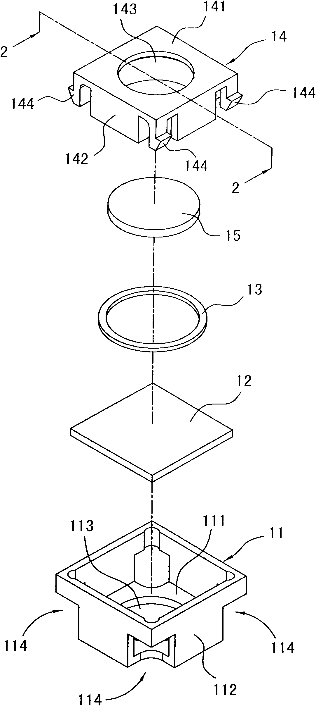
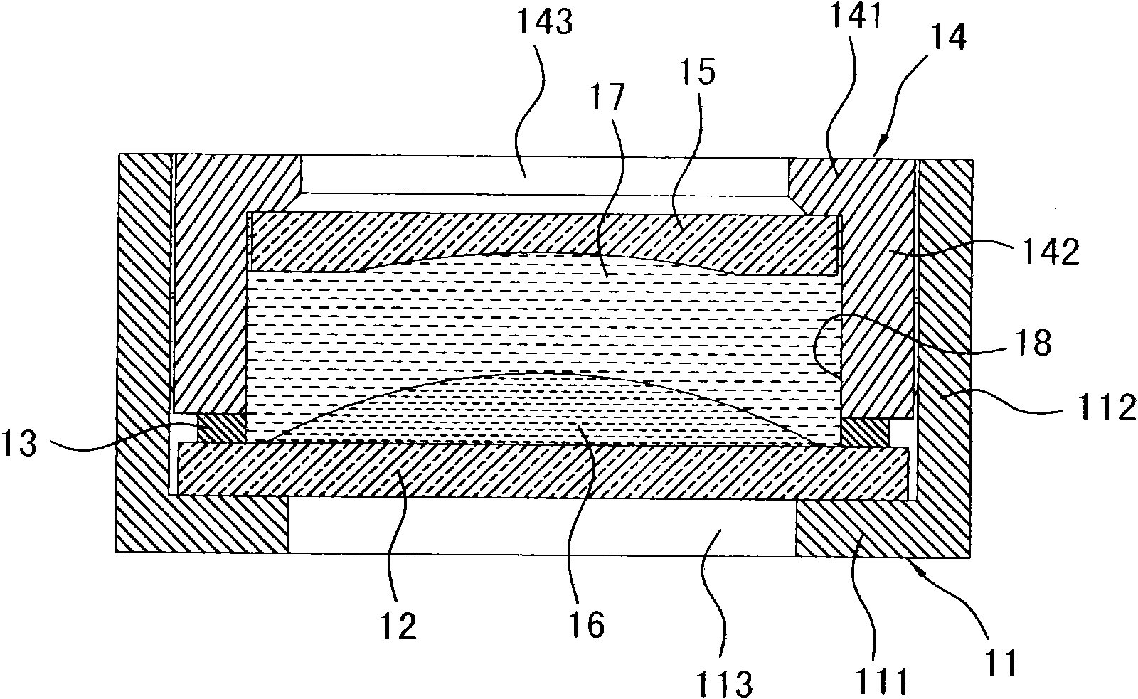
[0045] figure 1 and figure 2 As shown, it is the first preferred embodiment of the variable focus liquid lens element of the present invention, and the liquid lens element mainly includes a lower lens base 11, a light-transmitting electrode sheet 12, a rubber ring 13, an upper lens barrel 14, a transparent Light sheet 15, a first liquid layer 17 (see figure 2 ), and a second liquid layer 16 (see figure 2 ).

[0046] The lower mirror base 11 has a bottom wall 111 and a first surrounding wall 112 extending upward from the bottom wall 111 , and the bottom wall 111 has a lower mirror hole 113 . The lower mirror base 11 is made of plastic materials such as liquid crystal polymer (LCP), polycarbonate (polycarbonate; PC) and glass fiber mixture, polyvinyl toluene PVT (polyvinyl toluene PVT), or polyamide (polyamid...


PUM


Abstract

The invention discloses a liquid lens element, which comprises a lower lens base, a transparent electrode plate, a rubber ring, an upper lens cone, a transparent plate, a first liquid layer and a second liquid layer. The lower lens base is provided with a lower lens hole. The transparent electrode plate seals the lower lens hole. The rubber ring is arranged around the circumference of the transparent electrode plate. The upper lens cone is extended downwards to the rubber ring and provided with an upper lens hole. The transparent plate seals the upper lens hole; and the transparent plate, theupper lens cone and the transparent electrode plate define an accommodating setting space together. The second liquid layer is arranged in the accommodating setting space and positioned above the transparent electrode plate. The first liquid layer is arranged in the accommodating setting space and positioned above the second liquid layer.

Description

technical field [0001] The invention provides an optical element and its manufacturing method, especially a liquid lens (liquid lens) element and its manufacturing method. Background technique [0002] The liquid lens element includes two liquids packaged in a lens barrel. The two liquids are mutually immiscible and in contact with each other to form an interface with a predetermined curvature, which can refract the passing light. When a voltage is applied to one of the liquids, the curvature of the interface will change to change the refraction direction of the passing light, so that the liquid lens element has the function of optical zoom. [0003] Since the liquid is sealed in the lens barrel through two transparent sheets, and no air is allowed in the lens barrel to avoid affecting the optical performance, when the liquid is heated and expands, it will directly exert pressure on the lens barrel and the transparent sheet. It is easy to cause structural damage to the lens...

Claims


Application Information

Patent Timeline
IPC IPC(8): G02B3/12G02B3/14
Inventor 游昆洁徐仲凯林明杰苏铃达
Owner CREATIVE SENSOR INC
Learn More