Thermoelectric heat exchanger

a heat exchanger and thermoelectric technology, applied in the direction of thermoelectric devices with peltier/seeback effects, basic electric elements, electric apparatus, etc., can solve the problems of reducing heat transfer area, and reducing heat transfer efficiency

Inactive Publication Date: 2008-04-10
RAYTHEON TECH CORP
View PDF6 Cites 20 Cited by
  • Summary
  • Abstract
  • Description
  • Claims
  • Application Information

AI Technical Summary

Benefits of technology

[0007]The present invention provides a thermoelectric effects materials based energy transduction device, for selectively providing conversions between electrical and thermal energies, and has a both first plurality of n-type layers each formed of n-type electrical conductivity material and each having thermoelectric effects properties and a first plurality of p-type layers each formed of p-type electrical conductivity material and each having thermoelectric effects properties. The first plurality of p-type layers is interleaved in spatial positions with the first plurality of n-type layers along a spatial curve to form a first spatial position sequence of these layers. In addition, there is a first plurality of passageway structures each being thermally conductive and each having passageways therethrough extending between two sides thereof. There is a passageway structure from this first plurality thereof positioned between members of each overlapped pair of succeeding layers in the first spatial position sequence thereof such that either the passageway structures in the first plurality thereof are each electrically conductive and are each in electrical contact with that n-type layer and that p-type lay

Problems solved by technology

There are several difficulties with this arrangement.
First, providing the precise placement and interconnection of each of the semiconductor elements of the device in the layer row is relatively time consuming and expensive.
Secondly, each of the mechanical junctions needed in providing the thermal couplings from the layer row to the fluids provides a contact resistance which results in a decrease in heat transfer effectiveness.
Additionally,

Method used


Image

  • Thermoelectric heat exchanger
  • Thermoelectric heat exchanger
  • Thermoelectric heat exchanger

Examples


Embodiment Construction

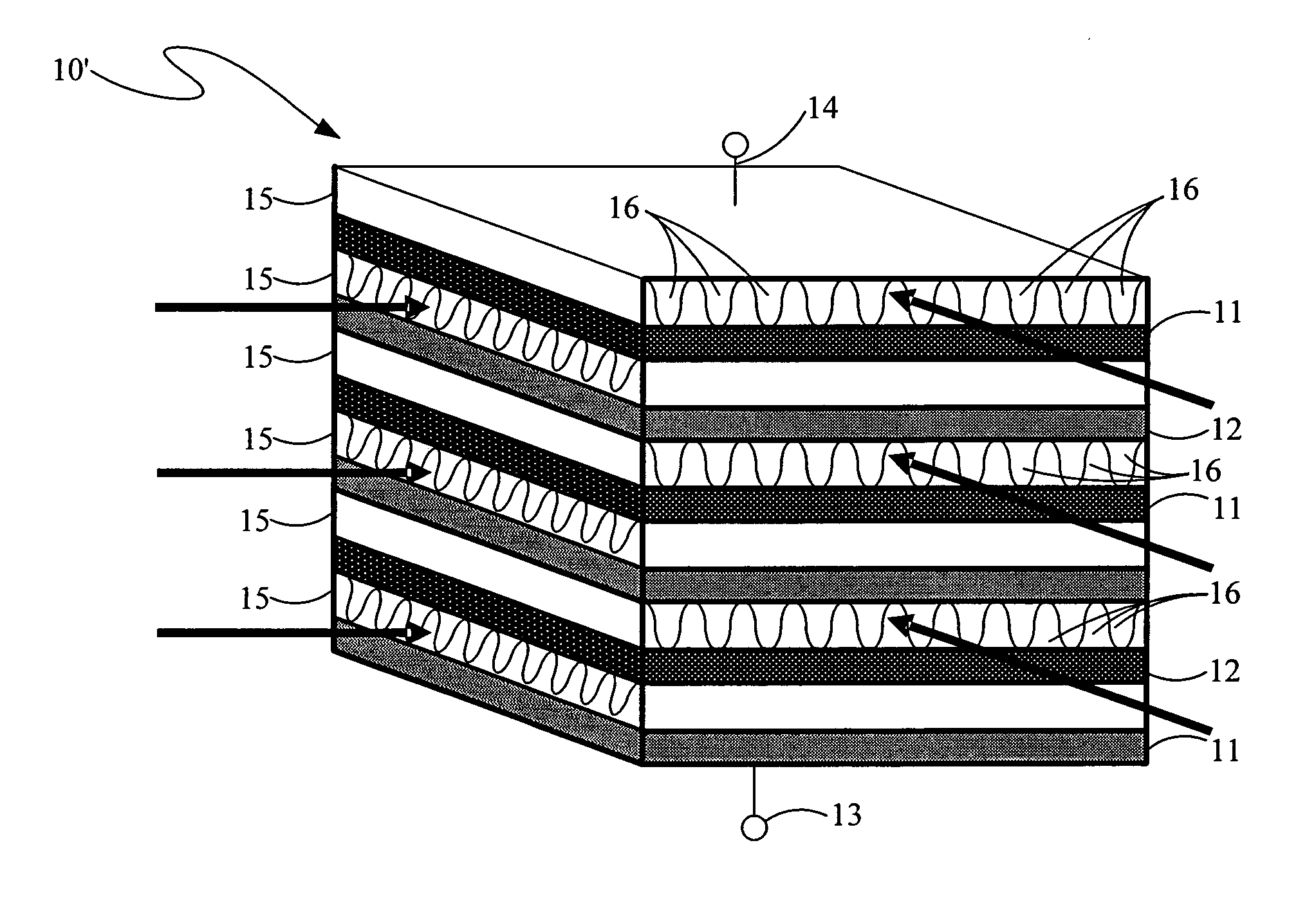
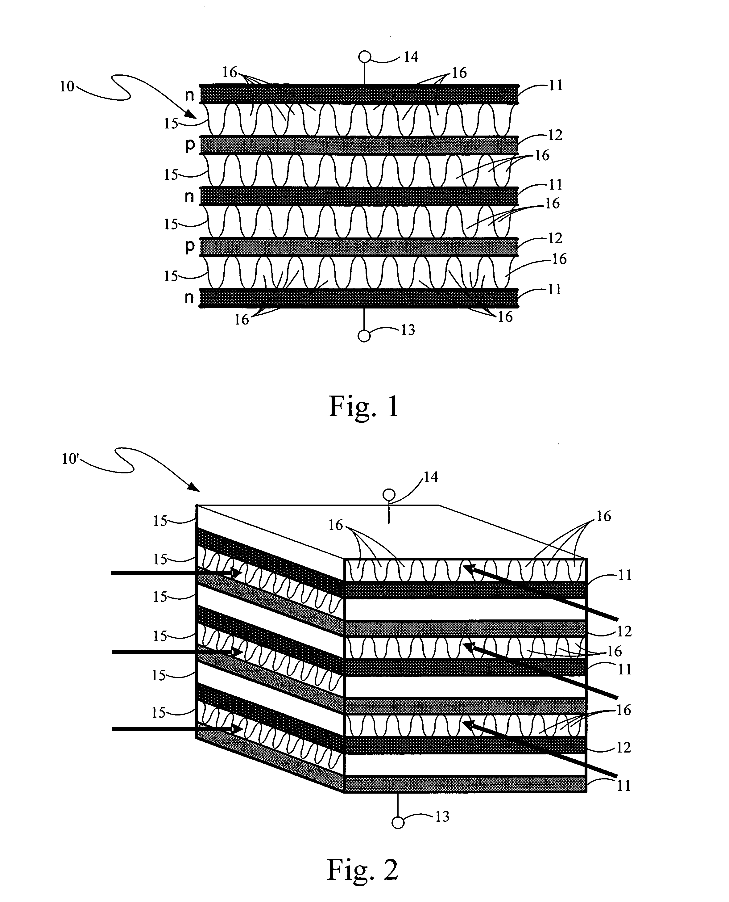
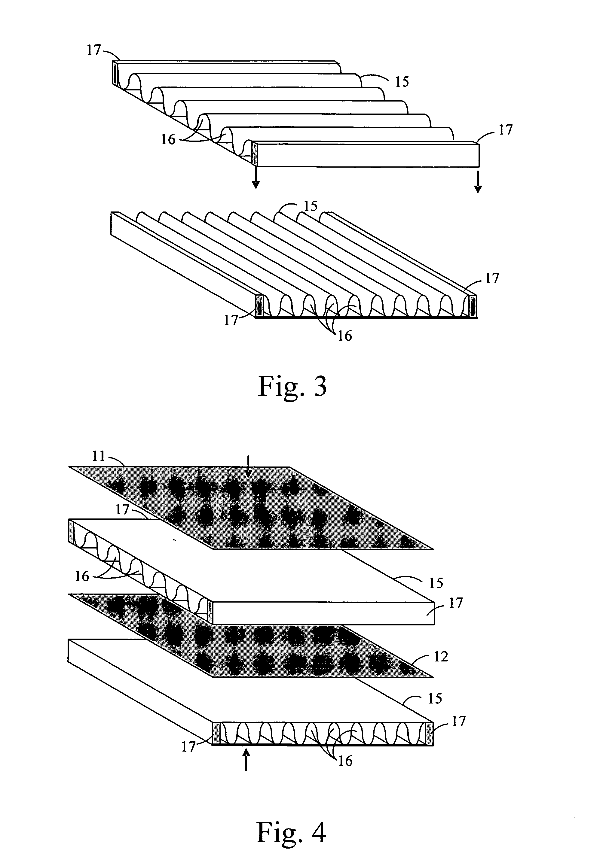
[0022]The present invention, as shown in part in the layer diagram side view thereof in FIG. 1, is a thermoelectric heat exchanger device, 10, for using thermal energy therein to generate electrical power or for using electrical power therein to provide cooling or heating, or both, depending on the materials used in the structure and the electrical currents or thermal gradients applied therein. Thermoelectric heat exchanger device 10 is formed of a succession of semiconductor or semimetal material layers provided therein in a spatial position sequence of alternating electrical conductivity types, p and n types, this spatial sequence of layers being distributed along a spatial curve, typically a line. Succeeding pairs of layers, each of a different conductivity type, are electrically interconnected to one another by a corresponding one of a plurality of electrical conductors positioned therebetween but are also spatially separated from one another by a corresponding one of a pluralit...


PUM


Abstract

A thermoelectric effects materials based energy transduction device, for selectively providing conversions between electrical and thermal energies having interleaved n-type conductivity material layers having thermoelectric effects properties and a first plurality of p-type conductivity material layers each having thermoelectric effects properties. There is a first plurality of passageway structures each being thermally conductive and each having passageways therethrough extending between two sides thereof with such a passageway structure from this first plurality thereof positioned between members of each overlapped pair of succeeding layers.

Description

BACKGROUND OF THE INVENTION[0001]The present invention relates to thermoelectric effects and thermoelectric materials in solid state thermoelectric devices and, more particularly, to the use of such materials with heat exchangers in such devices.[0002]Increasing demand for energy and for transfers of energy is characteristic of modern societies. These trends are likely to continue in view of the ever increasing numbers of consumers, the ensuing increase in the numbers of appliances and vehicles used by those consumers, and the numbers and sizes of business entities supplying same.[0003]Such energy must often be converted from one kind to another and different kind in the supplying of that energy or the transferring of that energy. Solid state thermoelectric devices are useful for these purposes as they can convert electrical currents to corresponding thermal gradients (based on the Peltier effect in using an electric potential across a conductive material to attract heat energy carr...

Claims


Application Information

Patent Timeline
IPC IPC(8): H01L35/28
CPCH01L35/30H10N10/13
Inventor SIENEL, TOBIAS H.
Owner RAYTHEON TECH CORP
Why Eureka
Try Eureka