
End of life prediction of flash memory

a technology of flash memory and end of life prediction, which is applied in the field of memory devices, can solve the problems of current flash memory not having a way to notify a user when the erase-write cycle life is approaching or has been exceeded, and users are not able to predict when their flash memory devices are about to fail

Active Publication Date: 2008-04-10
INT BUSINESS MASCH CORP
View PDF7 Cites 34 Cited by
  • Summary
  • Abstract
  • Description
  • Claims
  • Application Information

AI Technical Summary

Benefits of technology

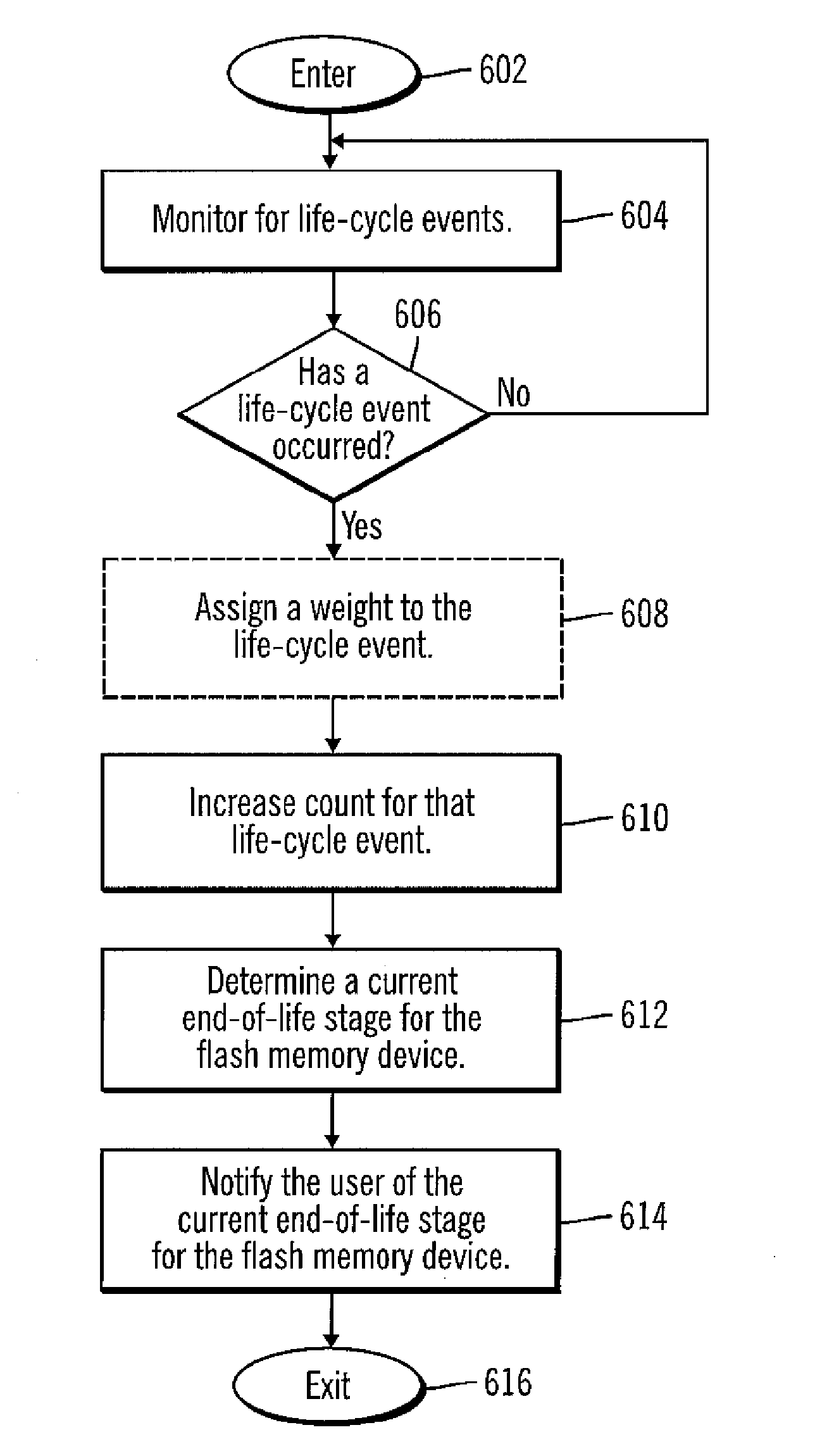
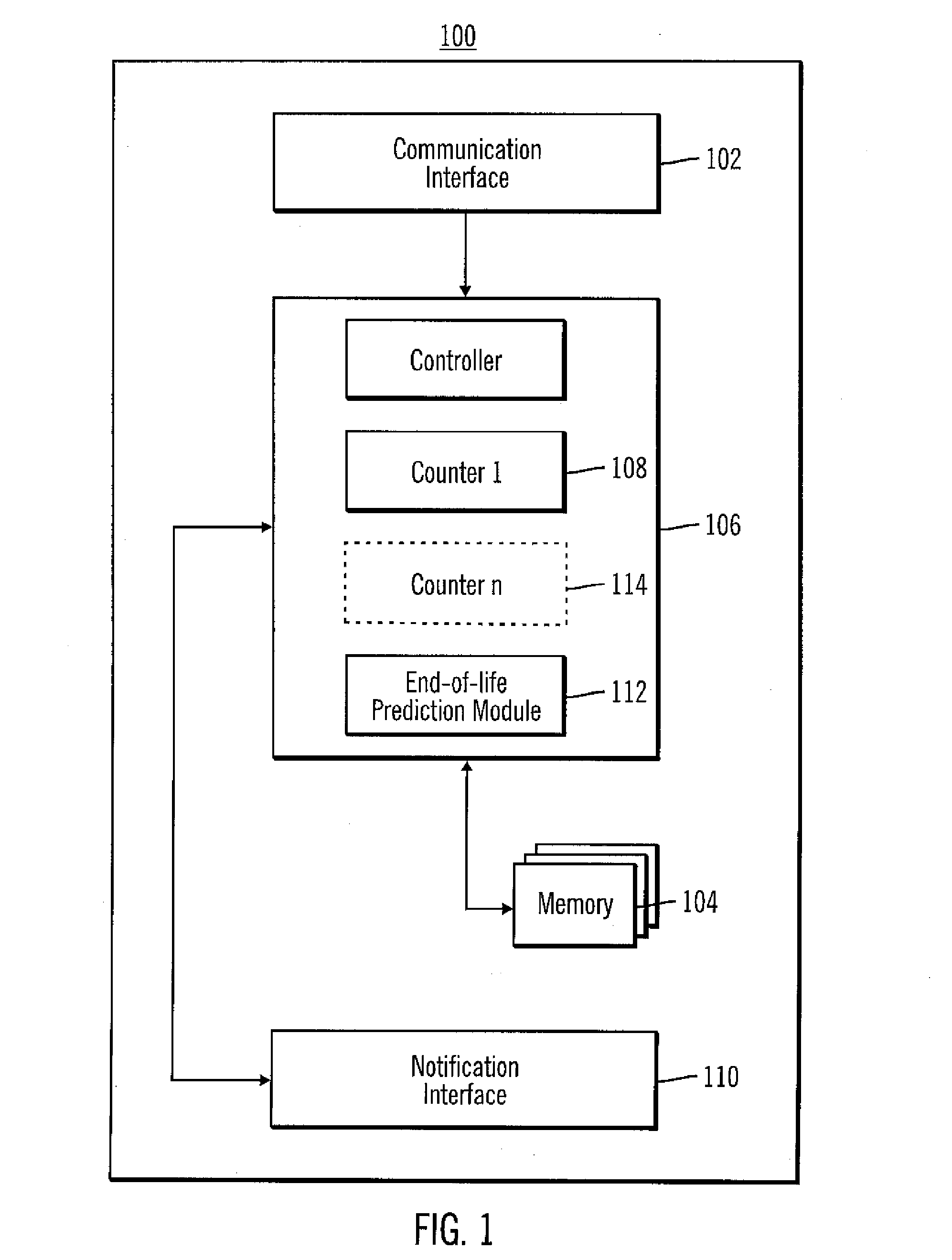
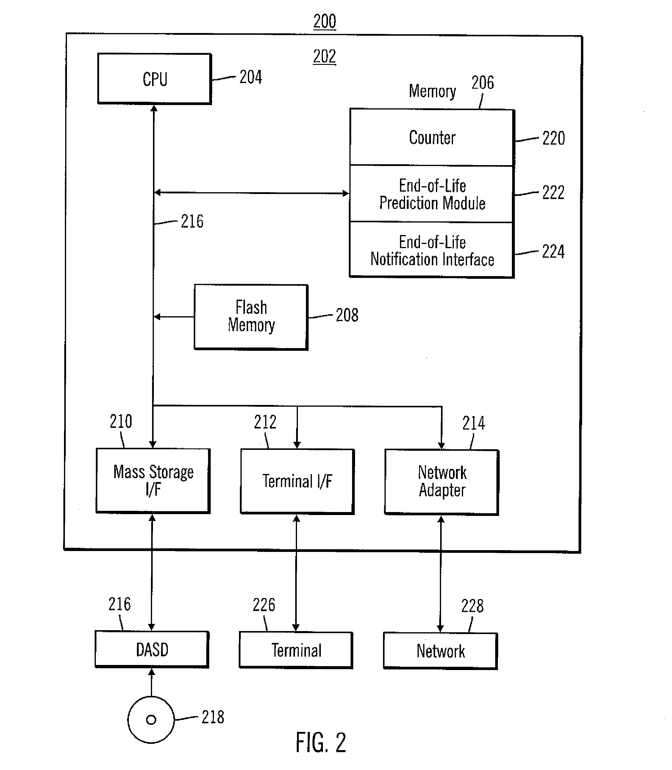
The present invention provides a method, electronic device, and computer readable medium for determining the end-of-life cycle of a flash memory. By detecting life cycle events associated with the flash memory and incrementing a counter, the method can determine the total number of occurrences for a given threshold. This information can be stored on the flash memory and reported to the user through a notification means. The technical effect of the invention is that users can be notified when their flash memory is reaching the end-of-life cycle, allowing them to transfer critical data off the memory before it fails.

Problems solved by technology

Flash memory is currently limited by the fact that it has a finite number of erase-write cycles.
Current flash memory does not have a way to notify a user of its erase-write cycle life is being approached or has been exceeded.
In other words, users are not able to predict when their flash memory devices are about to fail.
When a flash memory device fails, the device is inoperable and any data stored on the device is lost or corrupted.
Without being informed of a possible device failure, a user may continue to store critical information on the flash memory, which will be lost when the flash memory device fails.

Method used


Image

  • End of life prediction of flash memory
  • End of life prediction of flash memory
  • End of life prediction of flash memory

Examples


Embodiment Construction

[0018]The present invention as would be known to one of ordinary skill in the art could be produced in hardware or software, or in a combination of hardware and software. However in one embodiment the invention is implemented in software. The system, or method, according to the inventive principles as disclosed in connection with the preferred embodiment, may be produced in a single computer system having separate elements or means for performing the individual functions or steps described or claimed or one or more elements or means combining the performance of any of the functions or steps disclosed or claimed, or may be arranged in a distributed computer system, interconnected by any suitable means as would be known by one of ordinary skill in the art.

[0019]According to the inventive principles as disclosed in connection with the preferred embodiment, the invention and the inventive principles are not limited to any particular kind of computer system but may be used with any gener...


PUM


Abstract

Disclosed are a method, electronic device, and computer readable medium for determining an end-of-life stage of the flash memory. The method comprises detecting at least one life cycle event associated with a flash memory residing on an electronic device A counter that is associated with the life cycle event is then incremented. Based on the counter, a total number of occurrences for the one life cycle event is determined. The total number of occurrences for the at least one given threshold are also determined. A current life cycle stage of the flash memory is identified based at least in part on the determining if the total number of occurrences exceeds at least one given threshold. The life cycle stage is associated with the at least one given threshold. A user is then notified of the life cycle state of the flash memory.

Description

FIELD OF THE INVENTION[0001]The present invention generally relates to the field of memory devices, and more particularly relates to end of life prediction for flash memory.BACKGROUND OF THE INVENTION[0002]Flash memory provides non-volatile memory where blocks (which include multiple locations) of flash memory are erasable in a flash operation. Flash memory comprises cells, which are an array of floating gate transistors, for storing information. Traditionally one bit of information can be stored in each cell. However, some flash memory devices such as multi-cell memory devices can store more than one bit per cell. Two well-known types of circuitry that are present in flash memory cells are NAND and NOR.[0003]Flash memory is currently limited by the fact that it has a finite number of erase-write cycles. Current flash memory does not have a way to notify a user of its erase-write cycle life is being approached or has been exceeded. In other words, users are not able to predict when ...

Claims


Application Information

Patent Timeline
Patent Type & Authority Applications(United States)
IPC IPC(8): G06F19/00G06F17/40
CPCG06F11/008G06F11/3466G11C16/349G06F2201/88G06F12/0246
Inventor ASTIGARRAGA, TARAATHERTON, WILLIAM E.BROWNE, MICHAEL E.
Owner INT BUSINESS MASCH CORP
Learn More