High photoefficiency microalgae bioreactors

a bioreactor and microalgae technology, applied in bioreactors/fermenters, microorganisms, after-treatment of biomass, etc., can solve the problems of increasing the cost of hydrocarbon products, the process involved in creating biofuel from plant oils is expensive, and the large-scale algae harvest operation does not optimize the photoefficiency of algae in a cost-effective manner

Inactive Publication Date: 2008-04-17
GENERAL ATOMICS
View PDF25 Cites 38 Cited by
  • Summary
  • Abstract
  • Description
  • Claims
  • Application Information

AI Technical Summary

Benefits of technology

The patent describes a device that delivers a medium containing algae cells into a conduit, where a paddlewheel moves the medium at a specific speed. As the medium flows, barriers cause vortices that bring the algae cells to the surface of the fluid stream, where they can absorb light energy and convert it to chemical energy. This design maximizes the amount of light energy that the algae cells can receive, resulting in more efficient conversion of light to chemical energy.

Problems solved by technology

The technical problem addressed in this patent is to develop a system and method for optimizing the growth of algae cells in a bioreactor, by controlling the flow of the fluid stream in which they grow, and creating von Karman vortices to sequentially move the algae cells to the surface for predetermined intervals of time, in order to maximize the rate of growth and reduce costs associated with processing biofuel from plant oils.

Method used


Image

  • High photoefficiency microalgae bioreactors
  • High photoefficiency microalgae bioreactors

Examples


Embodiment Construction

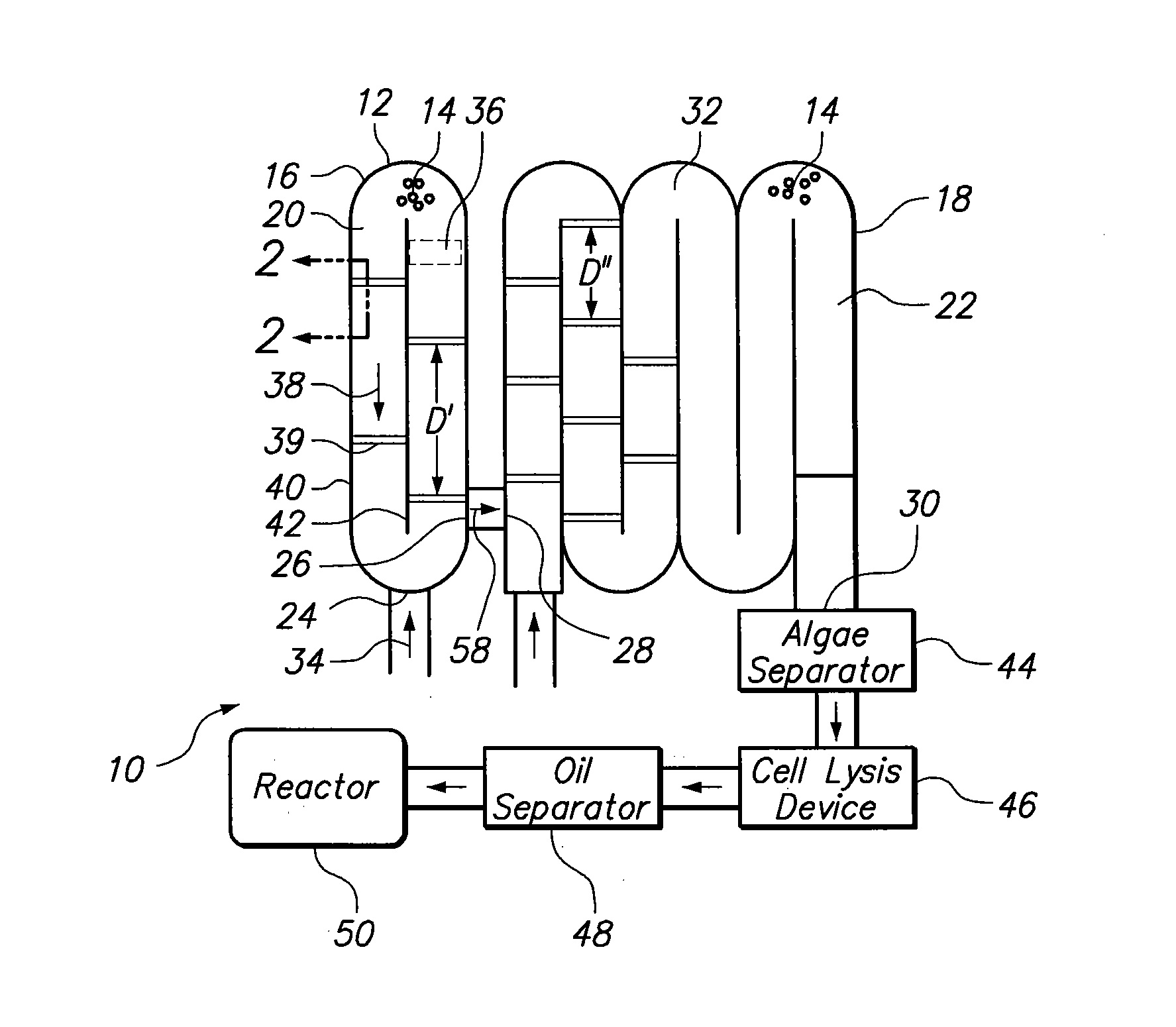
[0013]Referring initially to FIG. 1, a system for producing algae with improved photoefficiency is shown and generally designated 10. As shown, the system 10 includes a bioreactor 12 for growing algae cells (exemplary cells depicted at 14). Further, the bioreactor 12 is formed from a first stage reactor 16 and a second stage reactor 18. Preferably, the first stage reactor 16 is an open raceway chemostat and the second stage reactor 18 is an open raceway plug flow reactor. Each stage's reactor 16, 18 includes a conduit section 20, 22, respectively. As shown, the conduit section 20 includes an input port 24 and an output port 26. Also, the conduit section 22 includes an input port 28 and an output port 30. For purposes of the present invention, the output port 26 of the first stage reactor 16 and the input port 28 of the second stage reactor 18 are in fluid communication to create a conduit 32.

[0014]As further shown in FIG. 1, in the system 10, a medium (indicated by arrow 34) is rece...


PUM


Abstract

A system and method are provided for growing algae with improved photoefficiency. The system includes a bioreactor formed with a conduit for growing algae cells in a medium. Further, the system is provided with a means for moving the medium through the conduit at a predetermined fluid flow velocity. In order to ensure that algae cells are efficiently converting light energy to chemical energy, a plurality of barriers is positioned in the fluid stream. Specifically, the barriers are separated by predetermined distances to create von Karman vortices in the medium. As a result, algae cells are sequentially flowed to the surface of the fluid stream to receive light energy for predetermined intervals of time.

Description


Claims


Application Information

Patent Timeline
Owner GENERAL ATOMICS
Why Eureka
Try Eureka