Method for removing surface deposits in the interior of a chemical vapor deposition reactor

a technology of chemical vapor deposition reactor and surface deposits, which is applied in the direction of chemical vapor deposition coating, non-macromolecular adhesive additives, coatings, etc., can solve the problems of reducing the productive capacity of the chamber, the need to clean the chamber regularly, and the effectiveness of cleaning gases being limited

Inactive Publication Date: 2008-04-17
MASSACHUSETTS INST OF TECH
View PDF3 Cites 184 Cited by
  • Summary
  • Abstract
  • Description
  • Claims
  • Application Information

AI Technical Summary

Problems solved by technology

One of the problems facing the operators of chemical vapor deposition reactors is the need to regularly clean the chamber to remove deposits from the chamber walls and platens.
This cleaning process reduces the productive capacity of the chamber since the chamber is out of active service during a cleaning cycle.
Present cleaning gases are believed to be limited in their effectiveness due to low etch rates.
In order to partially obviate this limitation, current gases need to be run at an inefficient flow rate, e.g. at a high flow rate, and thus greatly contribute to the overall operating cost of the CVD reactor.
In turn this increases the production cost of CVD wafer products.

Method used


Image

  • Method for removing surface deposits in the interior of a chemical vapor deposition reactor
  • Method for removing surface deposits in the interior of a chemical vapor deposition reactor
  • Method for removing surface deposits in the interior of a chemical vapor deposition reactor

Examples


example 1

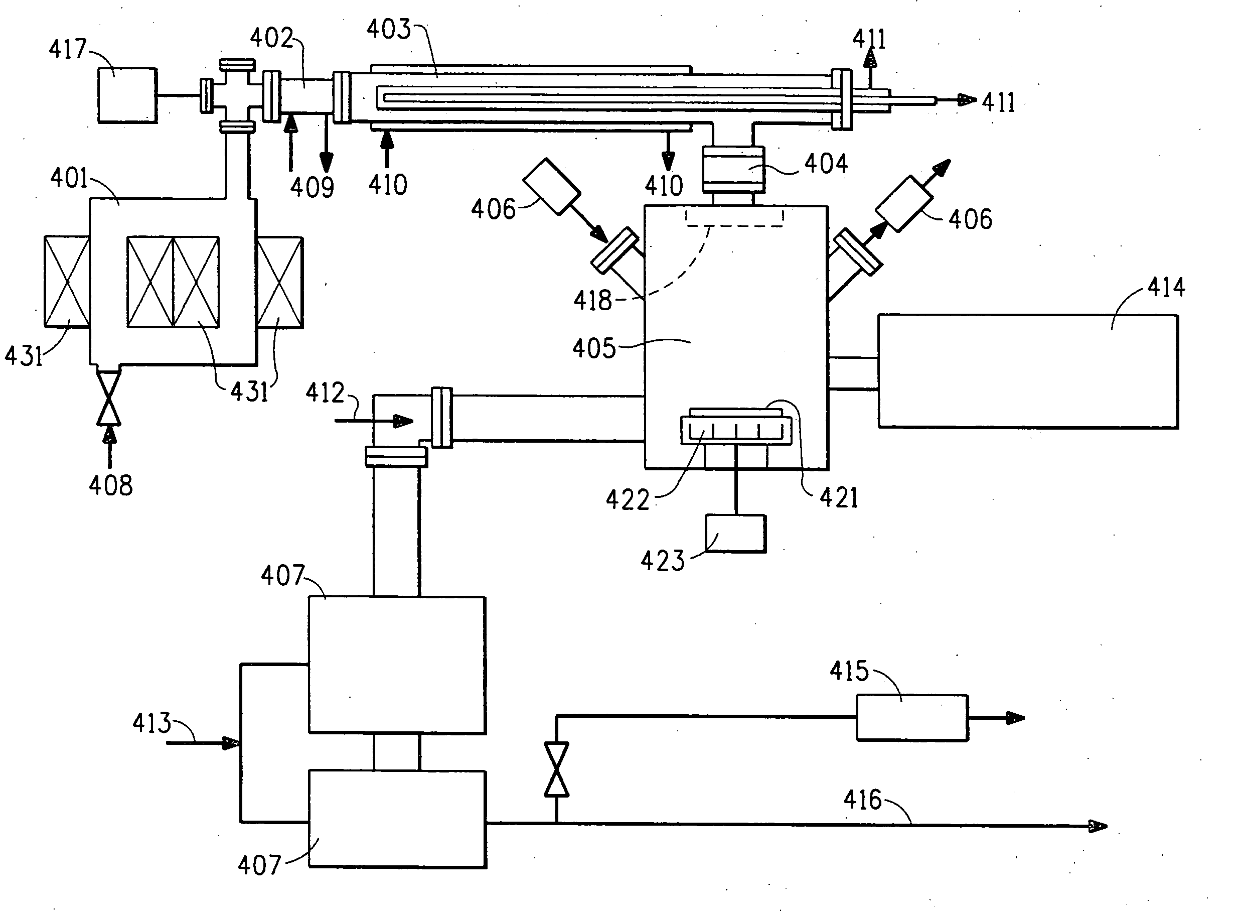
[0050] This example illustrates the effect of nitrogen addition on silicon dioxide etch rate and power consumption using a mixture of NF3, oxygen, and C2F6. Individual gas flow rates were as indicated, as measured in sccm. Remote chamber pressures were varied from 0.5 torr to 9 torr. The activated gas then entered the process chamber and etched the silicon dioxide surface deposits on the mounting with the temperature controlled at 250° C. Results are illustrated in FIG. 5.

example 2

[0051] The procedure of example 1 is followed, with the flow rate NF3 set at 650 sccm. Results are illustrated in FIG. 6.

example 3

[0052] This example illustrates the effect on etch rate and power consumption with and without a flow restricting device on the procedure of example 1 Gas flows and compositions were as indicated. Results are illustrated in FIGS. 7 and 8.


PUM

PropertyMeasurementUnit
poweraaaaaaaaaa
diameteraaaaaaaaaa
frequencyaaaaaaaaaa

Abstract

Disclosed is a deposition apparatus assembly comprising a deposition chamber, a remote chamber outside the deposition chamber for producing a reactive species from a precursor gas mixture, an activation source adapted to deliver energy into said remote chamber, a conduit for flowing the reactive species from said remote chamber to said deposition chamber and a flow restricting device interposed between said conduit and said remote chamber wherein said flow restricting device is cooled by an external source.

Description

CROSS REFERENCE(S) TO RELATED APPLICATION(S) [0001] This application claims the benefit of priority of U.S. Provisional Application 60 / 846,992, filed Sep. 25, 2006.BACKGROUND INFORMATION [0002] 1. Field of the Disclosure [0003] This disclosure relates in general to methods for removing surface deposits and an apparatus therefor. [0004] 2. Description of the Related Art [0005] One of the problems facing the operators of chemical vapor deposition reactors is the need to regularly clean the chamber to remove deposits from the chamber walls and platens. This cleaning process reduces the productive capacity of the chamber since the chamber is out of active service during a cleaning cycle. The cleaning process may include, for example, the evacuation of reactant gases and their replacement with an activated cleaning gas followed by a flushing step to remove the cleaning gas from the chamber using an inert carrier gas. The cleaning gases typically work by etching the contaminant build-ups ...

Claims


Application Information

Patent Timeline
Patent Type & Authority Applications(United States)
IPC IPC(8): C23C16/00
CPCC23C16/4405H01J37/32357C23C16/452
Inventor SAWIN, HERBERTBAI, BOAN, JU
Owner MASSACHUSETTS INST OF TECH
Why Eureka
Try Eureka