
Handheld programmer for lighting control system

a lighting control system and hand-held technology, applied in the direction of program control, electric programme control, instruments, etc., can solve the problems of limiting the amount of message traffic, causing delay in command time, and devices connected to the dali bus not being able to communica

Active Publication Date: 2008-04-17
LUTRON TECH CO LLC
View PDF46 Cites 68 Cited by
  • Summary
  • Abstract
  • Description
  • Claims
  • Application Information

AI Technical Summary

Problems solved by technology

A disadvantage of this single interface is that the bandwidth of the interface limits the amount of message traffic that can reasonably flow between the controller and the ballasts.
This can also create delays in times to commands.
If the bus power supply fails, the devices connected to the DALI bus will not be able to communicate.
Accordingly, configuring a prior art lighting control system can take a substantial amount of time.
Such a table of zones is not intuitive, and tasks associated with defining various lighting patterns based upon hundreds or even thousands of zones, many of which may include several or many lighting fixtures, is problematic.
While automatic methods for ballast replacement may be useful to replace a single ballast, it is ineffective to replace a plurality of ballasts, since each of the plurality of ballast will require respective setting and configuration information transmitted thereto.
Multiple unassigned ballasts cannot be distinguished from each other, and, accordingly, there is no way in the prior art to automatically provide respective setting and configuration information for each of a plurality of ballasts.

Method used


Image

  • Handheld programmer for lighting control system
  • Handheld programmer for lighting control system
  • Handheld programmer for lighting control system

Examples


Embodiment Construction

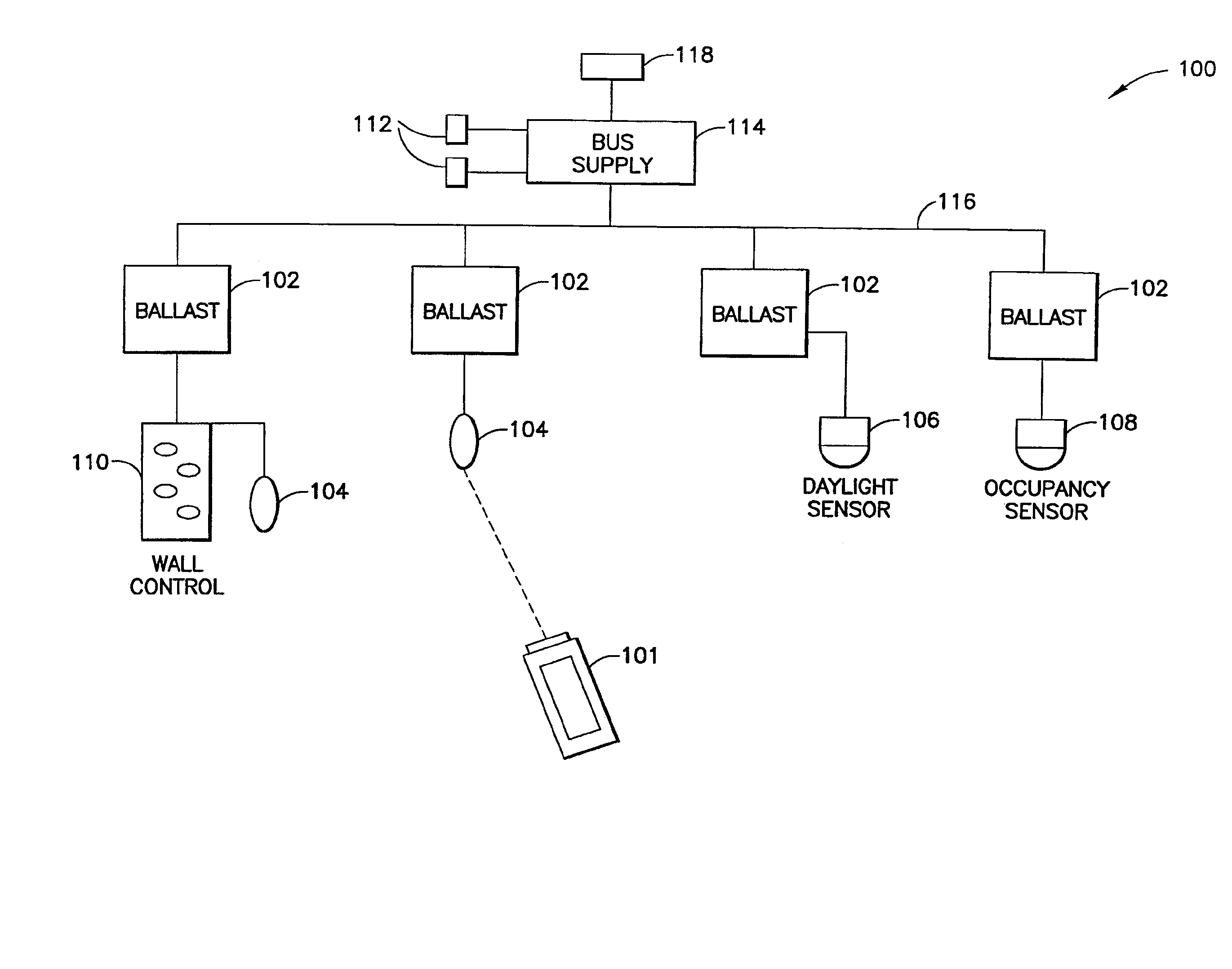
[0055] The foregoing summary, as well as the following detailed description of the preferred embodiments, is better understood when read in conjunction with the appended drawings. For the purposes of illustrating the invention, there is shown in the drawings an embodiment that is presently preferred, in which like numerals represent similar parts throughout the several views of the drawings, it being understood, however, that the invention is not limited to the specific methods and instrumentalities disclosed. Also, although the present invention is directed particularly to lighting controls, the present invention can be applied to communication signals for controlling the status of other kinds of devices, such as, for example, fan motors or motorized window treatments.

[0056] According to one aspect, the present invention is directed to a handheld programming device for a lighting control system including, for example, a plurality of programmable fluorescent electronic dimming ball...


PUM


Abstract

The invention regards a system and method for using a handheld programming device to configure a lighting control system wirelessly. In one embodiment, at least one device configured with a processing section is installed in the lighting control system. A communications receiver that is operable to receive a signal from the handheld programming device is also installed in the lighting control system, wherein the signal includes an instruction for configuring the lighting control system. Further, the signal is wirelessly sent from the handheld programming device to the communications receiver, and the instruction is transmitted from the communications receiver to a device in the system. The instruction functions to configure the lighting control system.

Description

CROSS-REFERENCE TO RELATED APPLICATION [0001] This application is a divisional of U.S. patent application Ser. No. 11 / 375,462, filed Mar. 13, 2006, entitled HANDHELD PROGRAMMER FOR LIGHTING CONTROL SYSTEM, which claims priority from U.S. Provisional Patent Application Ser. No. 60 / 661,055, filed Mar. 12, 2005, entitled HANDHELD PROGRAMMER FOR LIGHTING CONTROL SYSTEM, the entire contents of which are hereby incorporated by reference.BACKGROUND OF THE INVENTION [0002] 1. Field of the Invention [0003] The present invention relates generally to a multi-ballast lighting and control system, and, more particularly, to a handheld programmer for a lighting control system including a plurality of programmable fluorescent electronic dimming ballasts, occupancy sensors, daylight sensors and infrared receivers. [0004] 2. Description of the Related Art [0005] Remote control and monitoring of electrical / electronic devices, such as load control devices of a lighting control system, is known. For exa...

Claims


Application Information

Patent Timeline
Patent Type & Authority Applications(United States)
IPC IPC(8): G08B1/08G05B19/02
CPCH05B37/0272H05B47/195H05B47/1965
Inventor CASH, AUDWIN W.KUMAR, RISHI RAJRIGATTI, CHRISTOPHER J.VESKOVIC, DRAGANHEWSON, JOHN
Owner LUTRON TECH CO LLC
Learn More