Directed dipole antenna having improved sector power ratio (SPR)

a dipole antenna and sector power technology, applied in the field of antennas, can solve the problem that the optimal value of downtilt is not always predictable, and achieve the effect of optimizing horizontal plane radiation patterns and improving roll-o

Inactive Publication Date: 2008-04-17
COMMSCOPE TECH LLC
View PDF5 Cites 11 Cited by
  • Summary
  • Abstract
  • Description
  • Claims
  • Application Information

AI Technical Summary

Benefits of technology

[0006] It is an objective of the present invention to provide a dual polarized antenna array having optimized horizontal plane radiation patterns. One objective is to

Problems solved by technology

However, the optimum value of downtilt is not always

Method used


Image

  • Directed dipole antenna having improved sector power ratio (SPR)
  • Directed dipole antenna having improved sector power ratio (SPR)
  • Directed dipole antenna having improved sector power ratio (SPR)

Examples


Embodiment Construction

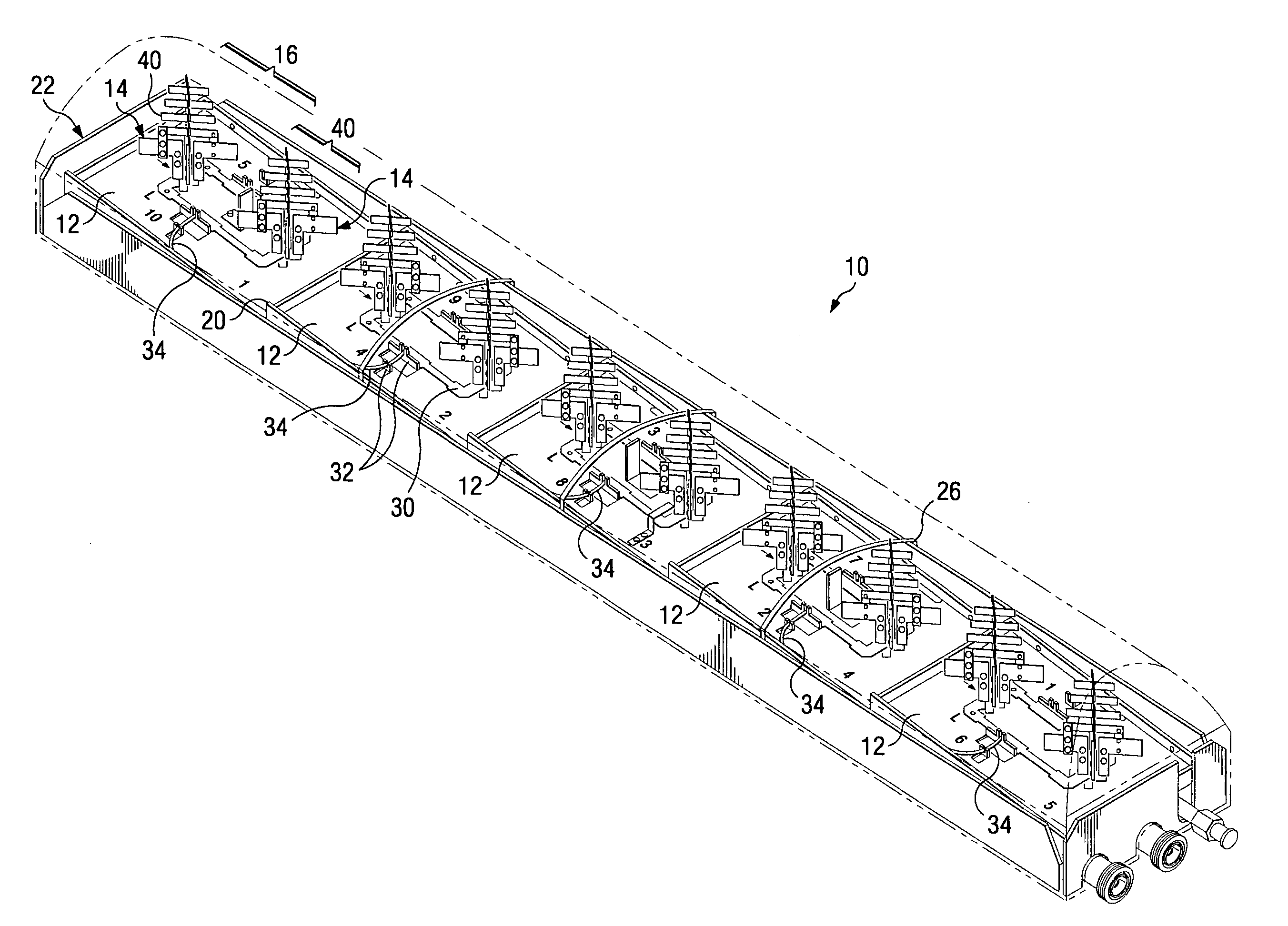
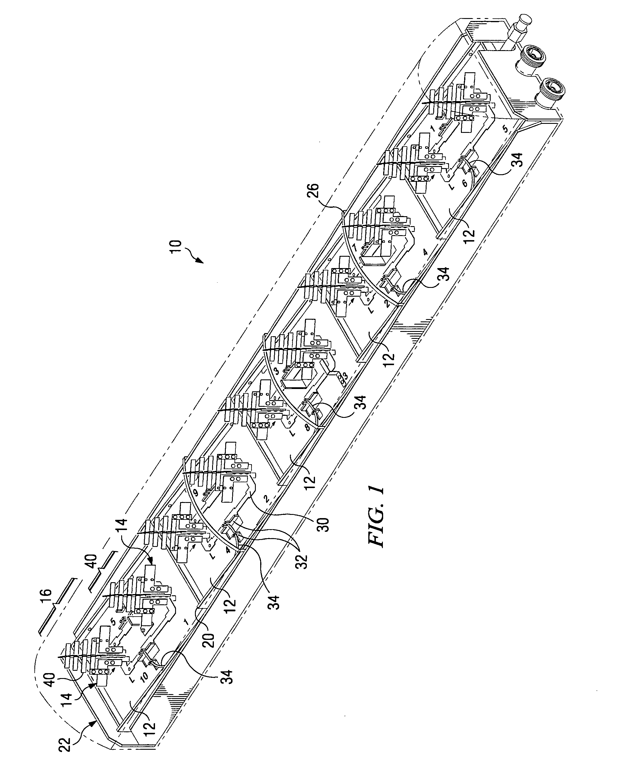
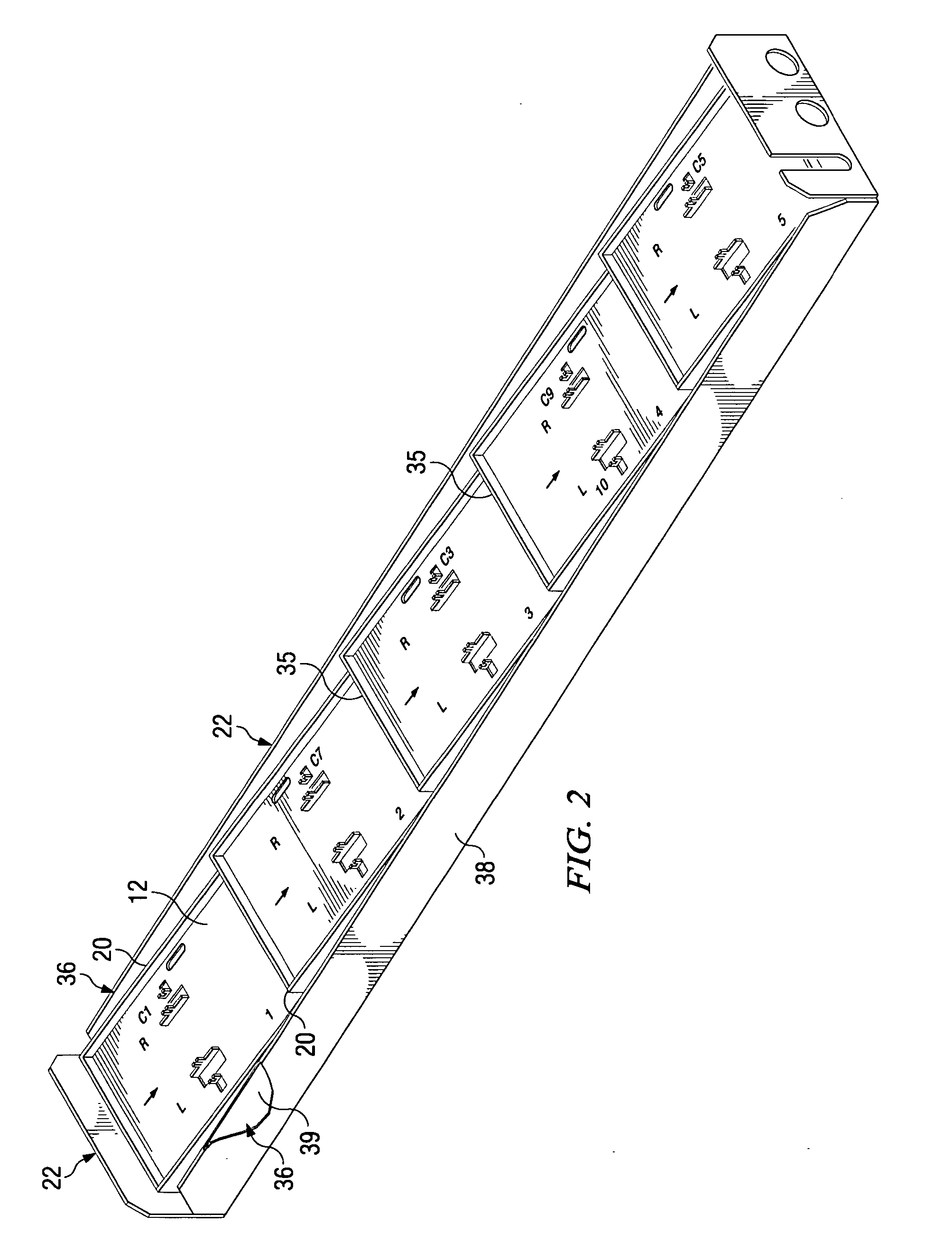
[0030] Referring now to FIG. 1, there is generally shown at 10 a wideband dual polarized base station antenna having an optimized horizontal radiation pattern and also having a variable vertical beam tilt. Antenna 10 is seen to include a plurality of element trays 12 having disposed thereon broadband slant 45 cross dipole (x-dipole) radiating elements 14 arranged in dipole pairs 16. Each of the element trays 12 is tilted and arranged in a “fallen domino” arrangement and supported by a pair of tray supports 20. The integrated element trays 12 and tray supports 20 are secured upon and within an external tray 22 such that there is a gap laterally defined between the tray supports 20 and the sidewalls of tray 22, as shown in FIG. 1 and FIG. 2. Each tray element 12 has an upper surface defining a groundplane for the respective dipole pair 16, and has a respective air dielectric micro stripline 30 spaced thereabove and feeding each of the dipole radiating elements 14 of dipole pairs 16, a...


PUM


Abstract

A dual polarized variable beam tilt antenna having a superior Sector Power Ratio (SPR). The antenna may have slant 45 degree dipole radiating elements including directors, and may be disposed on a plurality of tilted element trays to orient an antenna boresight downtilt. The directors may be disposed above or about the respective dipole radiating elements. The antenna has a beam front-to-side ratio exceeding 20 dB, a horizontal beam front-to-back ratio exceeding 40 dB, a high-roll off, and is operable over an expanded frequency range.

Description

CLAIM OF PRIORITY [0001] This application is a continuation of U.S. patent application Ser. No. 11 / 104,986 entitled DIRECTED DIPOLE ANTENNA filed Apr. 13, 2005, which claims priority of U.S. Provisional Application Ser. No. 60 / 577,138 entitled “Antenna” filed Jun. 4, 2004, and is a Continuation-in-Part (CIP) of U.S. patent application Ser. No. 10 / 737,214 filed Dec. 16, 2003, entitled “Wideband Dual Polarized Base Station Antenna Offering Optimized Horizontal Beam Radiation Patterns And Variable Vertical Beam Tilt”, which application claims priority of U.S. Provisional Patent Application Ser. No. 60 / 484,688 entitled “Balun Antenna With Beam Director” filed Jul. 3, 2003, and is also a Continuation-in-Part of U.S. patent application Ser. No. 10 / 703,331 filed Nov. 7, 2003, entitled “Antenna Element, Feed Probe, Dielectric Spacer, Antenna and Method of Communicating with a Plurality of Devices”, which application claims priority of U.S. Provisional Patent Application Ser. No. 60 / 482,689 ...

Claims


Application Information

Patent Timeline
IPC IPC(8): H01Q19/10
CPCH01Q19/10H01Q3/16
Inventor LE, KEVINMEYER, LOUIS J.BISIULES, PETE
Owner COMMSCOPE TECH LLC
Why Eureka
Try Eureka