Driving method and driving device of inkjet head

Active Publication Date: 2008-04-17
TOSHIBA TEC KK
View PDF3 Cites 2 Cited by
  • Summary
  • Abstract
  • Description
  • Claims
  • Application Information

AI Technical Summary

Benefits of technology

[0009]An object of the present invention is to provide an inkjet head driving method and an inkjet head driving device capable of reducing an effect of remaining vibration th

Problems solved by technology

However, according to principles of these documents, there has been a problem that control becomes complicated.
In addition, there has been a problem that print speed is lowered when t

Method used


Image

  • Driving method and driving device of inkjet head
  • Driving method and driving device of inkjet head
  • Driving method and driving device of inkjet head

Examples


first embodiment

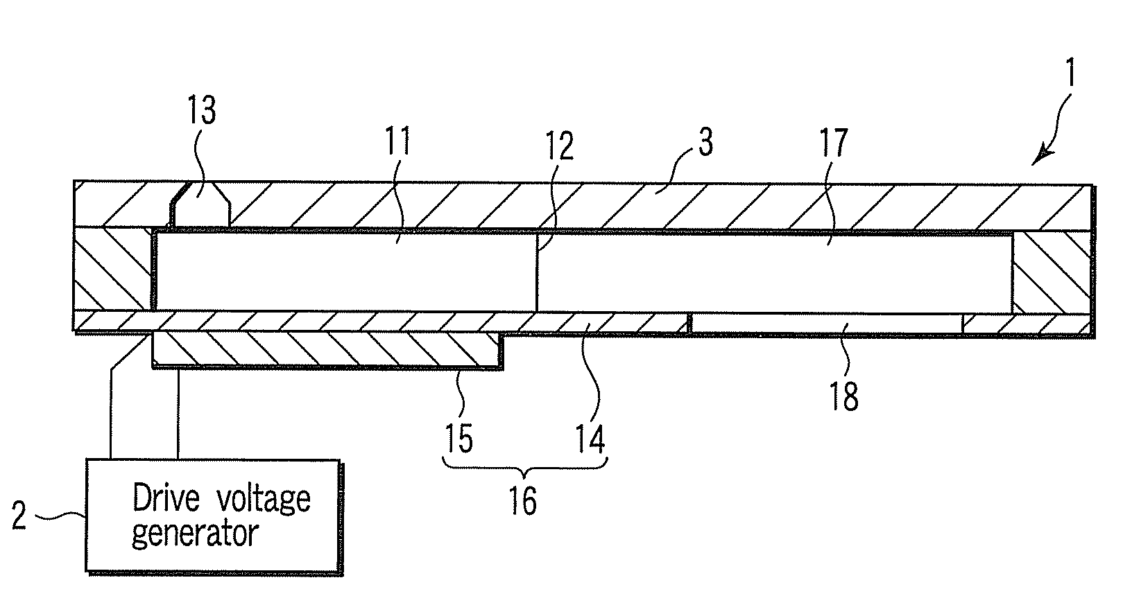
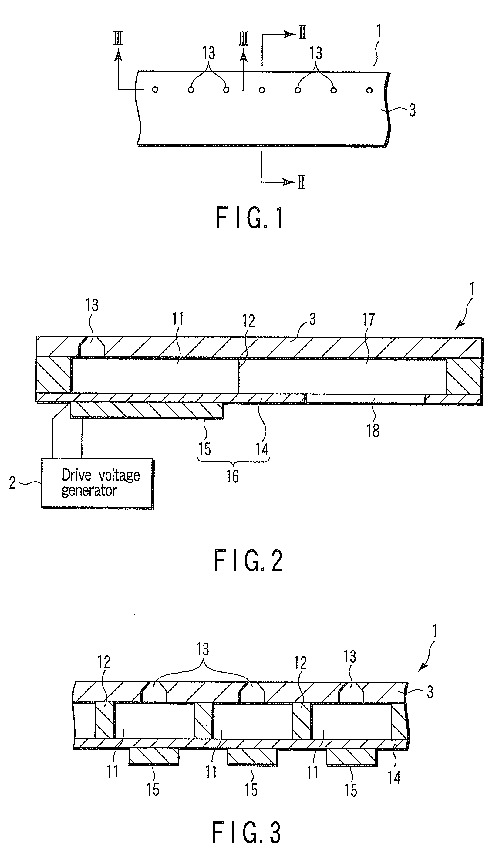
[0026]FIG. 1 shows an appearance of a front view of an inkjet head 1 of the inkjet recording apparatus. FIG. 2 shows a cross-sectional structure of the inkjet head 1 located along the II-II line shown in FIG. 1 together with a drive voltage generator. FIG. 3 shows a cross-sectional structure of the inkjet head 1 cut along the III-III line shown in FIG. 1. The inkjet recording apparatus includes the inkjet head 1 and a drive voltage generator 2. The inkjet head 1 includes a plurality of nozzles 13 that eject one or more ink droplets to print a dot of a tone corresponding to the number of the ink droplets, a plurality of pressure chambers 11 communicated with the nozzles 13 respectively, a common ink chamber 17 that supplies ink to the pressure chambers 11, and a plurality of actuators 16 that change volumes of the pressure chambers 11 via a diaphragm 14 by respectively according to drive voltages. The drive voltage generator 2 is provided for applying a series of drive pulse signals ...

second embodiment

[0055]In an inkjet recording apparatus of the present embodiment, the inkjet head 1 has the identical configuration as the first embodiment. The drive voltage generator 2 is configured to apply the drive pulse signals different from those in the first embodiment to the piezoelectric element 15 of each of the actuators 16.

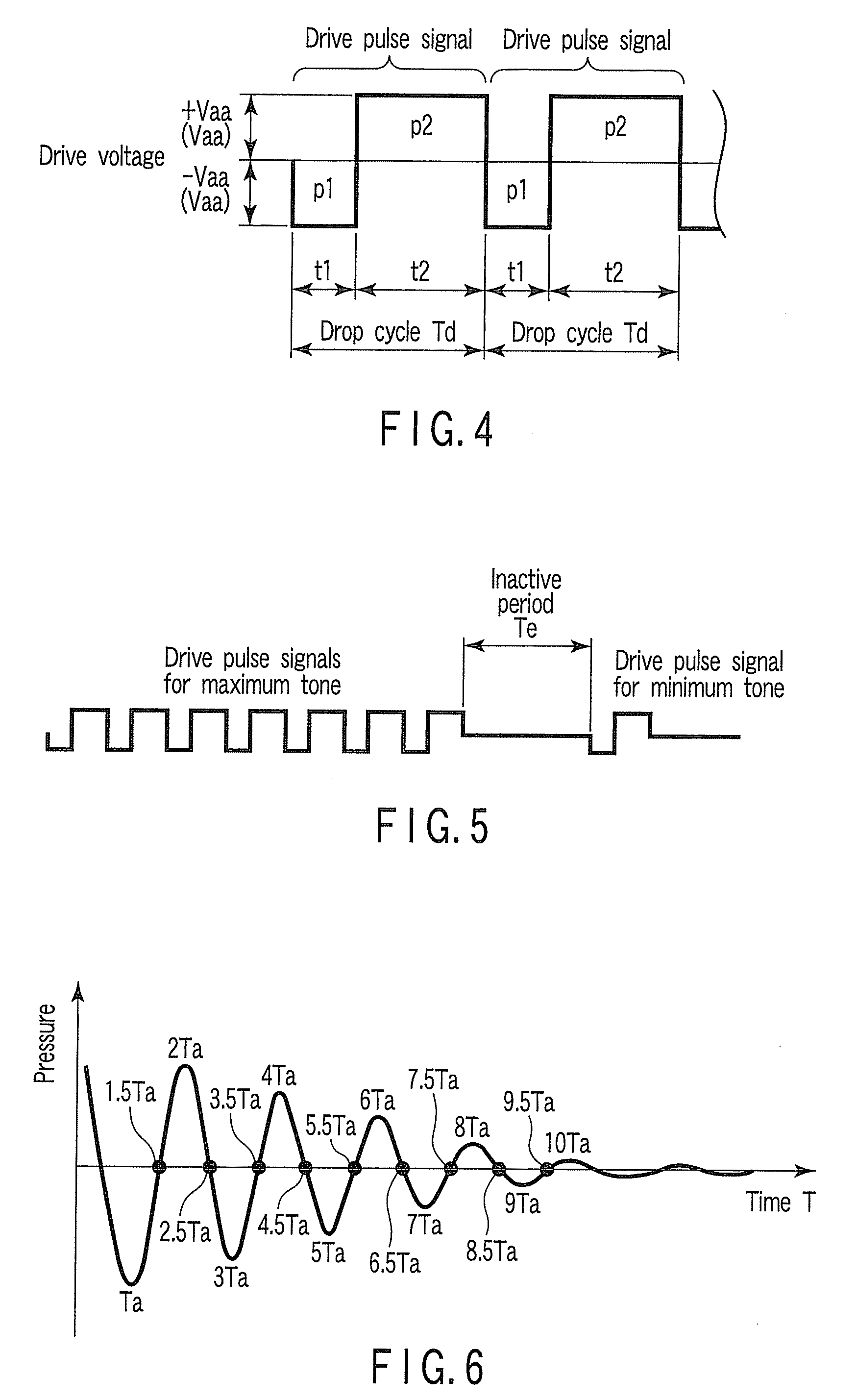
[0056]The drive voltage generator 2 generates the drive pulse signals of the number corresponding to the tones of a dot to be printed, where the drive pulse signals are set at output time Tdk (where k (natural number)=1, 2, 3, . . . N (N is the number of ink droplets for the maximum tone)). For example, the output times Td1, Td2, Td3, Td4, Td5, Td6, and Td7 of the drive pulse signals for the maximum tone differ from each other as shown in FIG. 8. The inactive period Te is set at Te=(0.5+m)×Ta (where m (natural number)=1, 2, 3, . . . ) as similar to the first embodiment. Here, it is preferable that m≦10 is established.

[0057]The cycle time (inverse of the drive freque...


PUM


Abstract

An inkjet recording apparatus includes actuators provided in an inkjet head, and a drive voltage generator that drives each actuator. The drive voltage generator is configured to set the cycle time Tc, the drop cycle Td, the number of ink droplets N for a maximum tone, and the inactive period Te in a relationship of Tc=Td×N+Te, set the drop cycle Td and the inactive period Te, by referencing pressure propagation time Ta in relationships of Td=n×Ta (where n=1, 2, 3, . . . ) and Te=(0.5+m)×Ta (where m=1, 2, 3, . . . ), and make an output timing of the final drive pulse signal for a dot of a tone other than the maximum tone coincide with an output timing of the final drive pulse signal for the maximum tone.

Description

CROSS-REFERENCE TO RELATED APPLICATIONS[0001]This application is based upon and claims the benefit of priority from prior Japanese Patent Application No. 2006-277950, filed Oct. 11, 2006, the entire contents of which are incorporated herein by reference.BACKGROUND OF THE INVENTION[0002]1. Field of the Invention[0003]The present invention relates to a driving method and a driving device of an inkjet head that ejects one or more ink droplets to print a dot of a tone corresponding to the number of the ink droplets.[0004]2. Description of the Related Art[0005]An inkjet recording apparatus of a multi-drop type is conventionally known. The inkjet recording apparatus includes an inkjet head that successively ejects one or more ink droplets for printing a dot, and a drive voltage generator that drives an inkjet head. The inkjet head has a nozzle plate on which a plurality of nozzles are arranged in one direction, a plurality of pressure chambers that are communicated with the nozzles respec...

Claims


Application Information

Patent Timeline
IPC IPC(8): B41J29/38
CPCB41J2/04573B41J2/04581C09K21/12B41J2/04595B41J2/04588
Inventor NORIGOE, TAKASHI
Owner TOSHIBA TEC KK
Why Eureka
Try Eureka