Method and apparatus for airway compensation control

a compensation control and airway technology, applied in the field of airway compensation control, can solve the problems of excessive lung distension, inability or inadvisable to move the patient to a laboratory or into and out of a body box for the determination of functional residual capacity, and so on. the effect of functional residual capacity

Active Publication Date: 2008-04-17
GENERAL ELECTRIC CO
View PDF13 Cites 119 Cited by
  • Summary
  • Abstract
  • Description
  • Claims
  • Application Information

AI Technical Summary

Benefits of technology

[0020]The foregoing provides an attending clinician with significant information for assessing the state of, and trends in, the functional residual capacity of the patient, as well as the relationship between the patient's residual capacity and the other factors, so that the clinician can fully discern the functional residual capacity condition of the patient.
[0021]With respect to assisting the clinician in adequately determining an optimal PEEP for the patient, as noted above, the apparatus and method of the present invention determines and displays relat

Problems solved by technology

But in many cases, patients that could benefit from a determination of functional residual capacity are so seriously ill as to not be breathing spontaneously but by means of a mechanical ventilator, such as a critical care ventilator.
This circumstance has heretofore proven to be a significant impediment in obtaining functional residual capacity information from such patients.
Additionally, the patient's illness may also make it impossibl

Method used


Image

  • Method and apparatus for airway compensation control
  • Method and apparatus for airway compensation control
  • Method and apparatus for airway compensation control

Examples


Embodiment Construction

The Mechanical Ventilator and Airway Gas Module

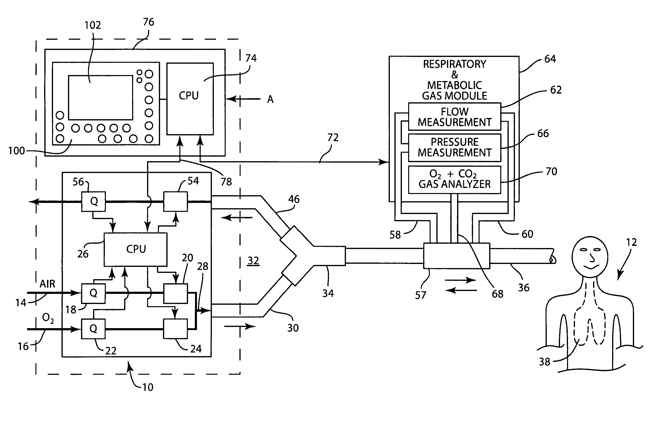
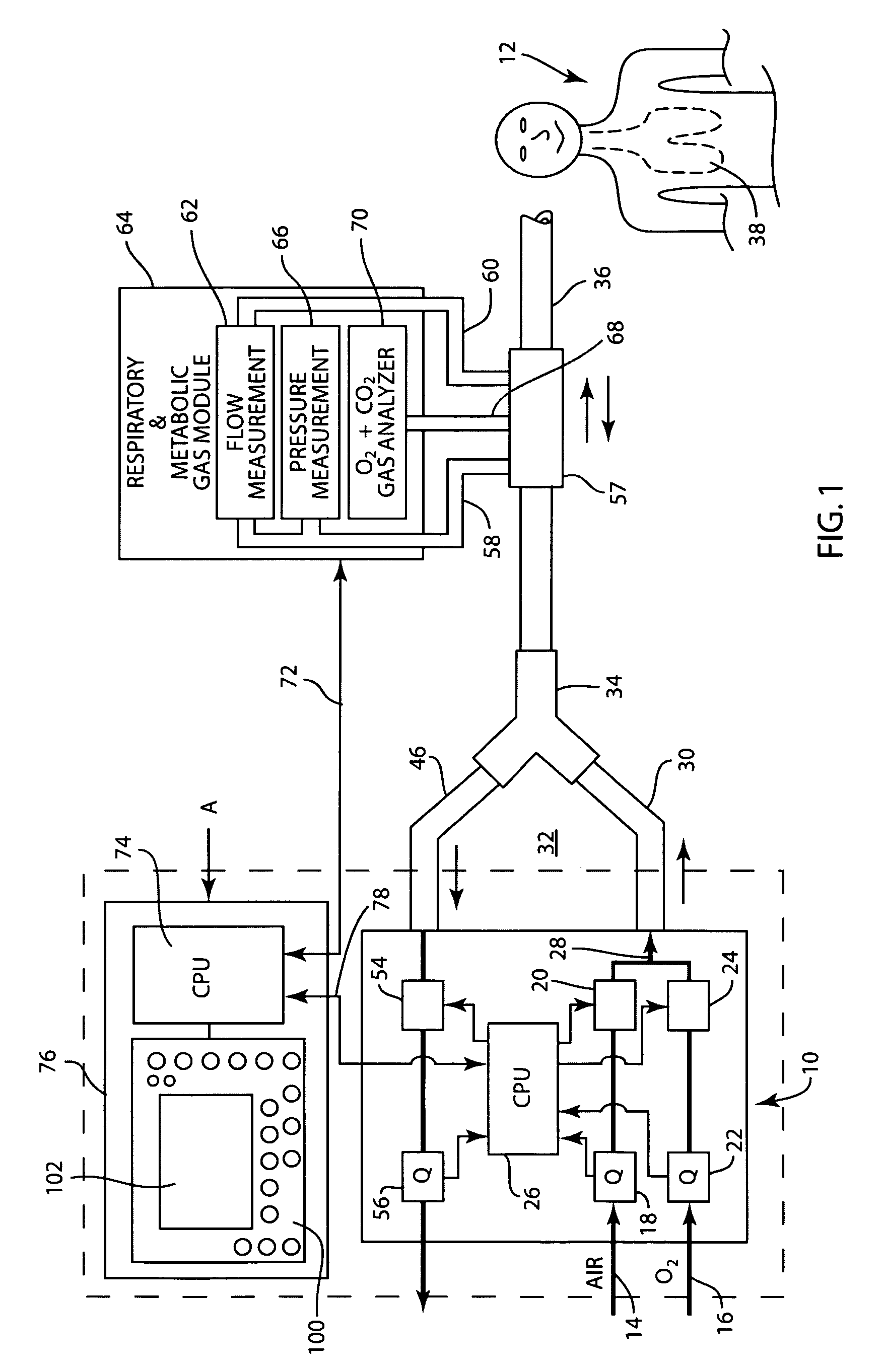
[0040]FIG. 1 shows mechanical ventilator 10 for providing breathing gases to patient 12. Ventilator 10 receives air in conduit 14 from an appropriate source, not shown, such as a cylinder of pressurized air or a hospital air supply manifold. Ventilator 10 also receives pressurized oxygen in conduit 16 also from an appropriate source, not shown, such as a cylinder or manifold. The flow of air in ventilator 10 is measured by flow sensor 18 and controlled by valve 20. The flow of oxygen is measured by flow sensor 22 and controlled by valve 24. The operation of valves 20 and 24 is established by a control device such as central processing unit 26 in the ventilator.

[0041]The air and oxygen are mixed in conduit 28 of ventilator 10 and provided to inspiratory limb 30 of breathing circuit 32. Inspiratory limb 30 is connected to one arm of Y-connector 34. Another arm of Y-connector 34 is connected to patient limb 36. During inspiration, patient ...


PUM


Abstract

A ventilator for ventilating a patient also assists a clinician in determining a suitable PEEP for the patient. For this purpose, a graph or tabular display of a series of different value PEEPs and corresponding functional residual capacities of the patient may be provided. Or, the relationship between lung compliance and a series of different values of PEEP may be provided. Or, the amount of the lung volume recruited/de-recruited at various levels of PEEP may be determined for use in selecting a desired PEEP. To this end, the functional residual capacity of the lungs is determined for a first PEEP level. The PEEP is then altered to a second level and a spirometry dynostatic curve of lung volume and pressure data is obtained. The lung volume on the dynostatic curve at a lung pressure corresponding to the first PEEP value is obtained. The difference between the functional residual capacity of the lungs at the first PEEP level and that determined from the dynostatic curve represents the lung volume recruited/de-recruited when changing between said first and second PEEPs.

Description

CROSS REFERENCE TO RELATED APPLICATION[0001]The present application claims the priority of U.S. Provisional Application No. 60 / 719,329, filed Sep. 21, 2005, and comprises a continuation-in-part of U.S. patent application Ser. No. 11 / 358,573, filed Feb. 21, 2006, which application also claims priority of U.S. Provisional Application No. 60 / 719,329.BACKGROUND AND SUMMARY[0002]The present invention relates to an apparatus and method for determining and displaying functional residual capacity data and other pulmonary parameters, such as positive end expiratory pressure (PEEP) data, for patients breathing with the aid of a mechanical ventilator, such as a critical care ventilator. The invention also determines and displays relationships between these and other parameters.[0003]Functional residual capacity (FRC) is the gas volume remaining in the lungs after unforced expiration or exhalation. Several methods are currently used to measure functional residual capacity. In the body plethysmo...

Claims


Application Information

Patent Timeline
IPC IPC(8): A61M16/00A61B5/08
CPCA61M16/0051A61M16/12A61M2016/0027A61M2016/0036A61M2016/0039A61M16/0402A61M2016/103A61M2202/0208A61M2205/502A61M2230/432A61M2230/435A61M2016/1025A61M16/042A61M16/0833A61M16/0858A61M16/0866A61M16/024
Inventor CHONCHOLAS, GARY J.TOBIA, RONALD L.
Owner GENERAL ELECTRIC CO
Why Eureka
Try Eureka