Method for cleaning the filters of a vacuum Cleaner and vacuum cleaner for carrying out said method

Active Publication Date: 2008-04-24
ALFRED KARCHER GMBH & CO KG
View PDF25 Cites 29 Cited by
  • Summary
  • Abstract
  • Description
  • Claims
  • Application Information

AI Technical Summary

Benefits of technology

[0026] In order that a great amount of external air can flow into the suction line within a very short time when the at least one closing valve is opened, it is of advantage if the valve body has at least one through-opening, which is delimited by at least one sealing element in the closed position of the valve body. The provision of a through-opening in the valve body makes it possible to make part of the external air pass through the through-opening when the closing valve is opened, while another part of the external air can flow around the outside of the valve body.
[0027] It is of advantage if the at least one valve seat has a number of through-openings, which are respectively delimited by at least one sealing element in the closed position of the valve body. For example, it may be provided that the valve seat comprises two annular through-openings disposed concentrically in relation to one another and the valve body has one annular through-opening in a radially intermediate

Problems solved by technology

However, this requires a complex construction, the two filters having to be of a considerable size to permit adequate suction flow during restricted suction operation.

Method used


Image

  • Method for cleaning the filters of a vacuum Cleaner and vacuum cleaner for carrying out said method
  • Method for cleaning the filters of a vacuum Cleaner and vacuum cleaner for carrying out said method
  • Method for cleaning the filters of a vacuum Cleaner and vacuum cleaner for carrying out said method

Examples


Example

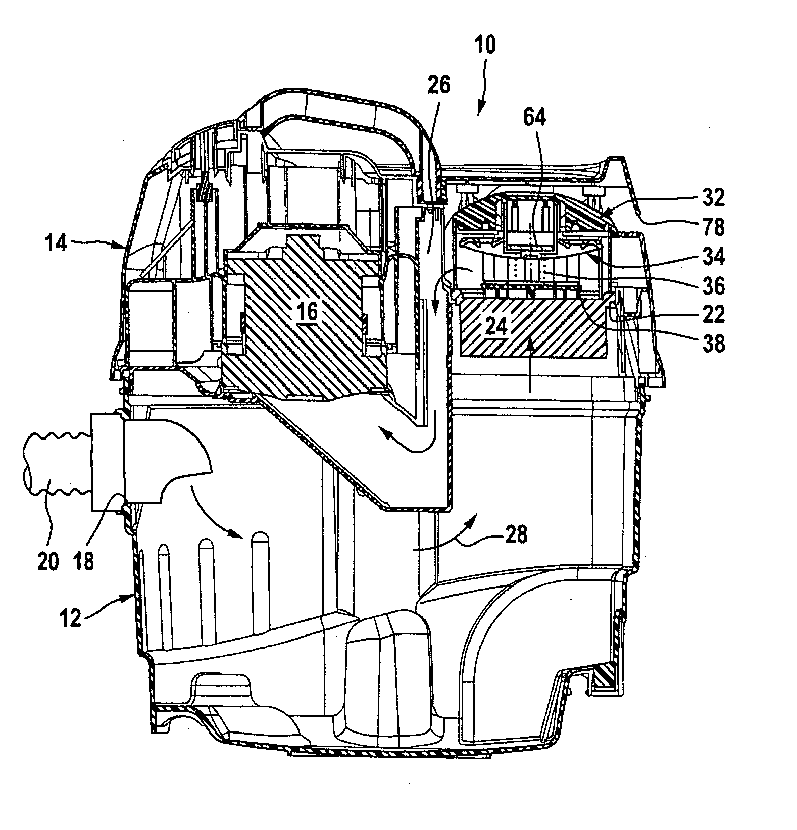
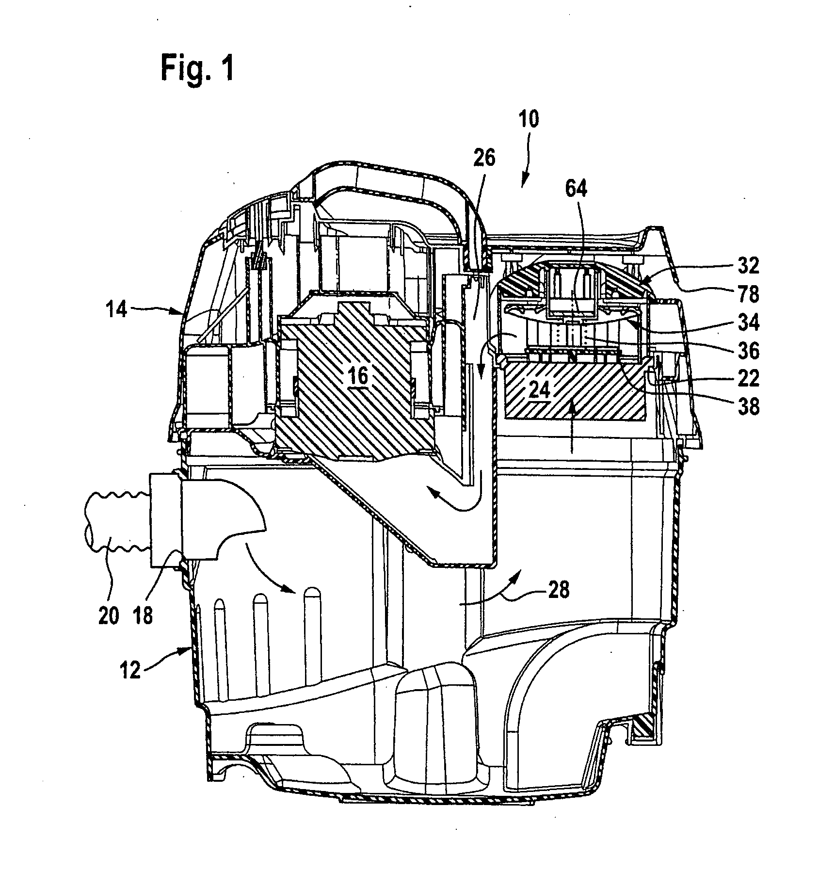
[0039] Schematically represented in the drawing is a vacuum cleaner 10, with a dirt collecting container 12, mounted on which is an upper part 14, which accommodates a suction unit 16. The dirt collecting container 12 has a volume of approximately 80 l, preferably a volume of about 30 l to approximately 80 l. It comprises a suction inlet 18, connected to which is a suction tube 20, at the free end of which (not represented in the drawing to achieve a better overview) a suction nozzle may be located. Alternatively, it may be provided that the suction tube 20 is connected to a working tool, for example a power drill or a masonry router, so that dust produced during the operation of the working tool can be sucked away.

[0040] The upper part 14 forms a suction outlet 22 for the dirt collecting container 12, a folded filter 24 being held on the suction outlet 22, which filter is followed by a suction line in the form of a suction channel 26, via which the folded filter 24 is in flow comm...


PUM

PropertyMeasurementUnit
Fractionaaaaaaaaaa
Timeaaaaaaaaaa
Timeaaaaaaaaaa

Abstract

The invention relates to a method for cleaning the filter of a vacuum cleaner which has a dirt collecting container with a suction inlet, to which a suction tube is connected, the dirt collecting container being connected to at least one suction unit via at least one filter and at least one suction line, and at least one closing valve closing an external air inlet, via which the suction line is connected to an external air supply, in which method, for cleaning the filter, the closing valve is opened and the side of the filter that is oriented away from the dirt collecting container is impinged upon by external air. To develop the method further in such a way that all the filters present can be flowed through by suction air during suction operation, but suction operation does not have to be noticeably interrupted for filter cleaning, it is proposed according to the invention that, by opening the closing valve, the negative pressure that forms within the suction tube at a distance of 3 cm from the suction inlet, on connecting a standard suction tube, is lowered for at least 10 ms and at most 150 ms to values of less than 40% of the value forming when the closing valves are closed. The invention also relates to a vacuum cleaner for carrying out the method.

Description

[0001] This application is a continuation of international application number PCT / EP2006 / 000671 filed on Jan. 26, 2006. [0002] The present disclosure relates to the subject matter disclosed in international application number PCT / EP2006 / 000671 of Jan. 26, 2006 and German application number 10 2005 017 702.6 of Apr. 11, 2005, which are incorporated herein by reference in their entirety and for all purposes.BACKGROUND OF THE INVENTION [0003] The invention relates to a method for cleaning the filters of a vacuum cleaner which has a dirt collecting container with a suction inlet, to which a suction tube is connected, the dirt collecting container being in connection with at least one suction unit via at least one filter and at least one suction line following the latter, and at least one closing valve closing an external air inlet, via which the suction line is connected to an external air supply, and in which method, for cleaning the at least one filter, at least one closing valve is o...

Claims


Application Information

Patent Timeline
IPC IPC(8): A47L9/20
CPCB01D46/10B01D46/4272B01D46/521B01D46/0086A47L9/20B01D46/0068B01D2279/55Y10S55/03B01D46/71
Inventor STEWEN, CHRISTIANHAEUSSERMANN, ULI
Owner ALFRED KARCHER GMBH & CO KG
Why Eureka
Try Eureka