Magnetic Nanoparticle Distribution in Microfluidic Chip

a microfluidic chip and magnetic nanoparticle technology, applied in nanostructure assemblies, laboratories, instruments, etc., can solve the problems of limited ability to control the distribution and movement of beads, obstruction of flow through tubes or microchannels, and non-trivial engineering to achieve them. achieve the effect of sufficient strength

Pending Publication Date: 2021-09-30
NAT RES COUNCIL OF CANADA
View PDF0 Cites 2 Cited by
  • Summary
  • Abstract
  • Description
  • Claims
  • Application Information

AI Technical Summary

Benefits of technology

[0022]Applicant has demonstrated that with a dense, high aspect ratio array of pillars coated with magnetizable material, arranged in rows within a microfluidic chamber, the rows aligned with an externally generated magnetic field of sufficient strength, distribution of MNPs to form a cloud region substantially limited to row spaces between the pillars, that a density of the MNPs across this space is sufficient that there are no visible gaps in the cloud between the row's pillars, and that no visible gaps appear, even when subjected to moderate flow thereacross.

Problems solved by technology

The most basic challenge in microfluidics in general, is to manipulate fluids in a controlled, repeatable manner, to achieve a desired process.
However, the engineering required to achieve these is non-trivial.
While the nanoparticles can be distributed randomly within a magnetic field, there is limited ability to control distribution and movement of the beads, because of the substantial limits on spatial and temporal variation of the magnetic fields within microfluidic chambers.
Rida notes a challenge with respect to maintaining a very localized high magnetic field gradient necessary for manipulating magnetic particles, on a microscopic scale in chips.
A resulting risk is obstruction of flow through the tube or microchannel, which is obviously problematic for achieving high surface area required for high fluid interaction potential.
The manipulation of magnetic particles is challenging for flow through arrangements of the magnetic particles, because too strong a flow tends to result in loss of particles, and too strong a magnetic field reduces fluid permeability, and does not necessarily provide a high surface area.
Rida still requires a fairly high number of particles, and is limited by the spatial and temporal control over magnetic fields within microfluidic channels.
It is known that when trapping micron scale targets, such as cells and bacteria, micron-scale particles do not provide sufficient surface area to volume capture area, and mobility to provide sufficient interaction probability with a sample stream.
Thus nanoparticles are preferred, but these are harder to control magnetically.
One of the problems with HGMS devices reported in the literature relate to the difficulties in releasing (cleaning) captured magnetic particles13, and in particular, the difficulty in preventing the magnetically labeled particles (cells) from permanent adhering to the magnetic elements.
However, the reported devices had difficulty releasing captured material due to the device design that is focused on creating magnetic field gradients as high as possible to maximize the capture forces, using solid magnetic wires21-23 as they provide maximum perturbation effects and non-uniformities (gradients) in the applied field.
However, in addition to the poor control of the capture regions due to an attractive capture force present everywhere on the surface of the wires / pillars,24 the large amounts of magnetic material employed usually possess strong remnant magnetization.
This creates significant capture forces that persist after removal of the external magnetic field which makes the release challenging.
While very high flow rates and associated drag forces may improve release of trapped particles, the removal in low flow regions and stagnation points on the pillars are particularly challenging, especially using only a single unidirectional liquid flush.
Various strategies, such as coating the magnetic material with PDMS,18 have been employed to improve magnetic release, which further complicates the process of making these MNPs, and increases the cost of these devices.
While this could potentially decrease the fabrication costs, the process suffers from low-throughput.
In addition to the difficulty of integrating soft magnetic materials in microfluidic channels, the devices reported in the literature suffered from small channel sizes and low density of magnetic microstructures.17-20 This typically results in low flow rates, low MNP capture capacity and limits use in higher throughput applications where a large number of magnetic beads have to be processed.

Method used


Image

  • Magnetic Nanoparticle Distribution in Microfluidic Chip
  • Magnetic Nanoparticle Distribution in Microfluidic Chip
  • Magnetic Nanoparticle Distribution in Microfluidic Chip

Examples


example

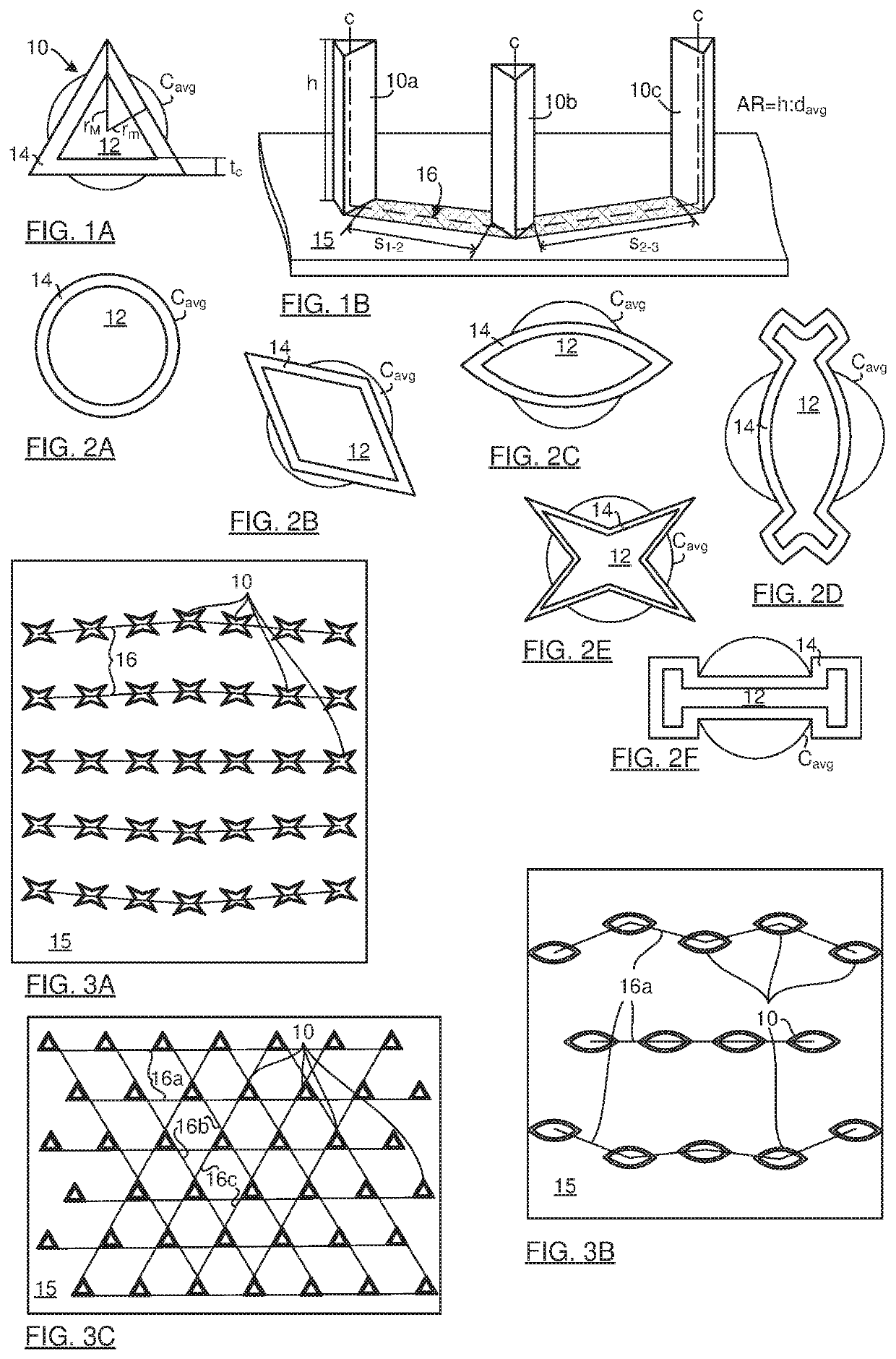
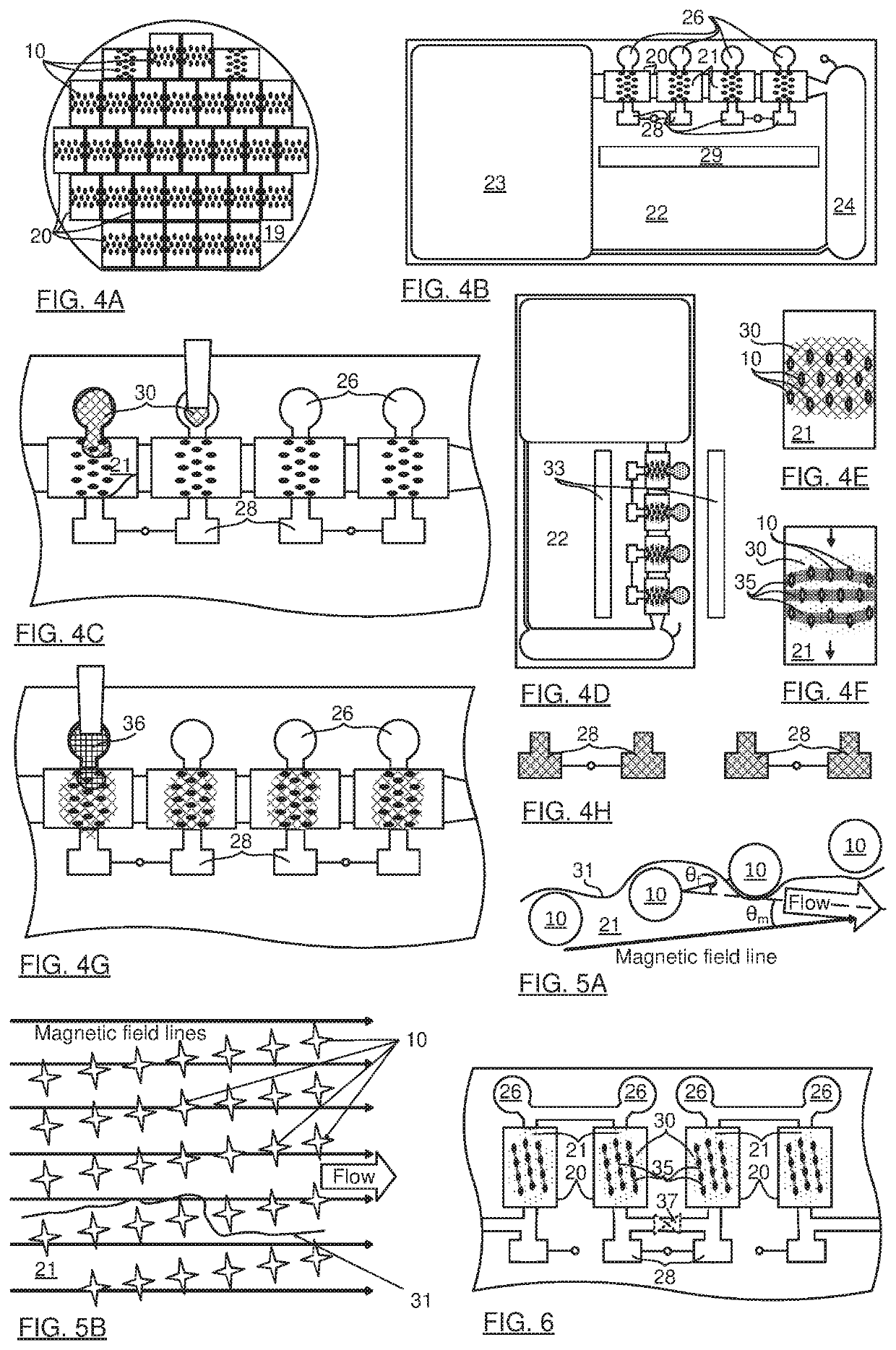
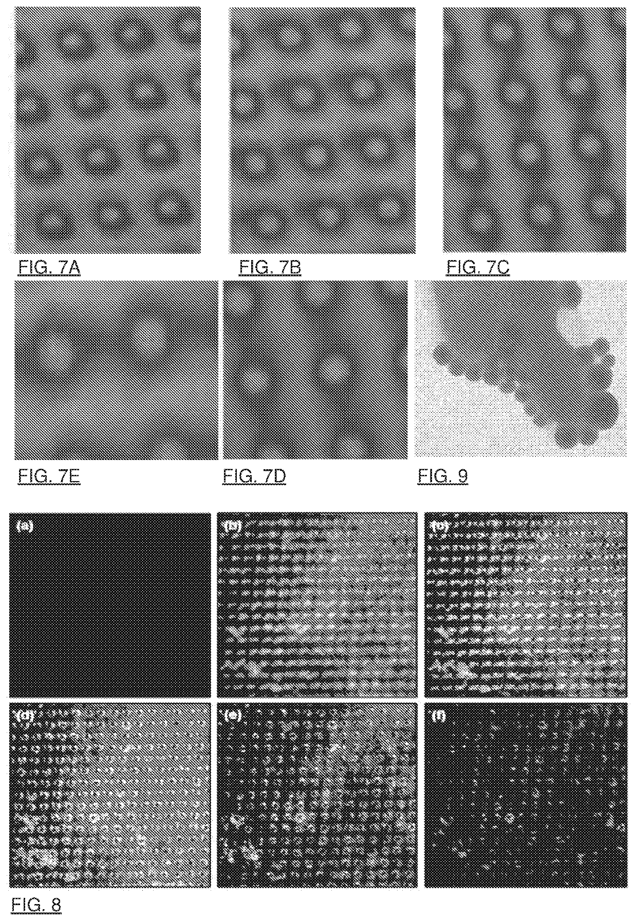
[0098]A magnetic capture device and apparatus, and it's fabrication has been described25, the entire content of which is incorporated herein by reference, including the supplementary information material. The magnetic capture device was filled with a 500 ng / ml concentration dispersion of superparamagnetic iron-oxide core silica shell nanoparticles. For present purposes, the NPs used were equivalent to NPs available from a variety of commercial suppliers. The chamber was 30 mm×17 mm. A pair of permanent magnets was initially placed at the opposite edges of the device. The magnets were 1 cm×5 cm×10 cm at a distance of 5.8 cm from each other. They generated a substantially uniform magnetic field within the capture region. We expect the graphs showing the magnetic field along different directions (for example FIG. 2 in the supplementary information material)25 to be representative of the fields produced with the present invention, except that the amplitudes are stronger with the higher ...


PUM

PropertyMeasurementUnit
diameteraaaaaaaaaa
diameteraaaaaaaaaa
thicknessaaaaaaaaaa

Abstract

The present invention relates into a device and method for controlling distribution of superparamagnetic nanoparticles (NPs) in a microfluidic chamber. By applying a strong magnetic field, localization of the NPs to inter-pillar spaces between soft magnetic coated micropillars is demonstrated, even with a modest fluid flow across the inter-pillar space. Flow splitting techniques are also provided to force particles to reliably interact with the NPs, specifically by using a Brevais lattice with a primative vector of 1°-15° with respect to flow direction. The pillars may have non-circular cross-sectional shape and be arranged to direct NP clouds more effectively. An array of the pillars has multiple axes for rotating NP cloud distributions in multiple orientations, allowing for a rotating magnetic field to move the NP cloud for mixing a fluid that is otherwise stationary.

Description

FIELD OF THE INVENTION[0001]The present invention relates in general to a technique for controlling magnetic nanoparticle distribution in a microfluidic chamber, and in particular to a kit, method and system for constraining magnetic nanoparticles to within spaces between micropillars.BACKGROUND OF THE INVENTION[0002]Microfluidic devices offer important opportunities for controlled movements of fluids. Tiny volumes of fluids are advantageous when small amounts of samples or reagents are available, where compact or portable assays are needed, where automation is essential for efficiency, and where fast reaction times are sought, especially in clinical diagnosis and biomedical research. A variety of capillarity, centrifugal, pneumatic, and electrostatic microfluidic devices have been provided to move fluids and perform various types of biochemical assays (which is to be understood broadly, and to include at least Lab on Chip (LOC), micro-total analysis systems (μTAS), organ on chip, a...

Claims


Application Information

Patent Timeline
Patent Type & Authority Applications(United States)
IPC IPC(8): B01L3/00H01F1/33B03C1/025
CPCB01L3/502707H01F1/33B03C1/025B82Y25/00B01L3/50273B01L3/502761B01L3/502715B82Y40/00G01N1/28G01N35/0098G01N2035/00237B01L2400/043B01L2300/0896B01L2200/0668B01L2400/086G01N33/54326B82B3/0052B01L2300/0877B82Y30/00B82Y35/00
Inventor MALIC, LIDIJACLIME, LIVIUBRASSARD, DANIELZHANG, XUEFENGVERES, TEODOR
Owner NAT RES COUNCIL OF CANADA
Why Eureka
Try Eureka