High-performance shielding sheet and preparation method thereof and coil module comprising the same

a shielding sheet and high-performance technology, applied in the field of electronic communication equipment manufacturing, can solve the problems of low charging efficiency, short effective charging distance, high cost, etc., and achieve the effect of improving wireless charging efficiency and optimizing the performance of the coil modul

Active Publication Date: 2021-08-31
SUNLINE PRINTING SHANGHAI ELECTRONICS CO LTD
View PDF8 Cites 0 Cited by
  • Summary
  • Abstract
  • Description
  • Claims
  • Application Information

AI Technical Summary

Benefits of technology

[0011]For solving the foregoing problems in the prior art, the present invention provides a shielding sheet having the advantages of improving the wireless charging efficiency and meeting the requirements for NFC applications, such that the performance of the coil module can be further optimized.
[0012]In order to achieve the above-mentioned purposes, the present invention adopts the following technical solutions. A high-performance shielding sheet, including at least one sheet, wherein the sheet includes at least one shielding layer formed of a soft magnetic material, and the shielding layer is a layer with low coercive force and low remanence; and at least one adhesive layer disposed on at least one side of the shielding layer; wherein the shielding layer includes a plurality of graphical slits, and the plurality of graphical slits divide the shielding layer into a plurality of graphical fragments; wherein the plurality of graphical slits are filled with the adhesive layer, enabling the plurality of graphical fragments to be separated from each other and have a good insulation property.
[0022]By adopting the above-mentioned technical solutions, the present invention has the following advantageous technical effects over the prior art. A high-performance shielding sheet and a coil module thereof is provided, wherein the shielding sheet consists of at least one shielding layer with low coercive force and low remanence, which may induce and restrict more magnetic lines of force to pass, thereby improving the electric charging conversion rate and increasing the charging efficiency; by adopting the shielding layer with low coercive force and low remanence, transmission loss may be reduced, and the uniformity of the electromagnetic wave transmission medium may be increased; and the coil module uses a shielding layer with low coercive force and low remanence and a coil having a width and a pitch in a certain range, which may help to improve wireless charging efficiency without affecting the application of near field communication.

Problems solved by technology

Wireless charging technology is developing rapidly in recent years, however, it has encountered many technical problems, such as low charging efficiency, high cost, and short effective charging distance, which restricts the usage scenarios and range of application of wireless charging.
If an electromagnetic shielding sheet is not provided in the wireless charging receiving end of the mobile phone, the wireless charging device cannot complete the charging task in a short distance.
The eddy current generates a magnetic field opposite to the direction of the magnetic field generated by the transmitting coil, and the opposite magnetic field and the magnetic field formed by the transmitting coil may cancel each other, so that the induced voltage received by the receiving coil drops; and the eddy current is converted into heat, causing the temperature of the mobile phone battery to rise, and thus leading to a harmful effect.
Due to the fact that the conventional magnetic shielding material only has an inhibitory effect on electromagnetic interference in a certain frequency band, and that it cannot yield a good electromagnetic shielding effect in a wider range, when a magnetic shielding sheet, formed of a certain magnetic material, is used in the mobile phone, it is often the case that the wireless charging or NFC are poorly applied.

Method used


Image

  • High-performance shielding sheet and preparation method thereof and coil module comprising the same
  • High-performance shielding sheet and preparation method thereof and coil module comprising the same
  • High-performance shielding sheet and preparation method thereof and coil module comprising the same

Examples


example 1

[0034]This example is an illustrative example of a high-performance shielding sheet according to the present invention.

[0035]A high-performance shielding sheet, including at least one sheet, wherein the sheet is a lamination structure and includes at least one shielding layer formed of a soft magnetic material, and the shielding layer is a layer with low coercive force and low remanence; and at least one adhesive layer adhered to at least one side of the shielding layer.

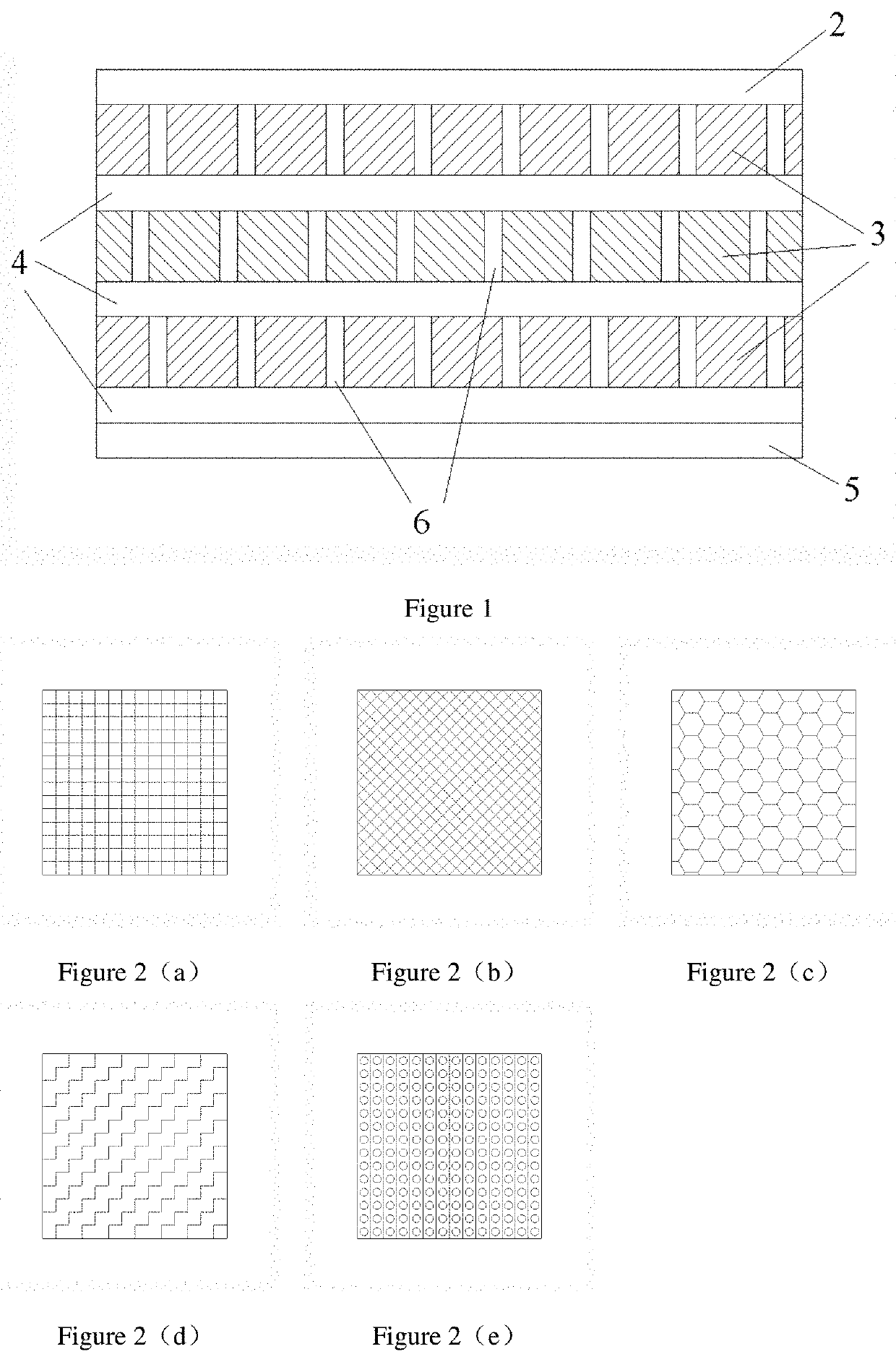
[0036]Specifically, as shown in FIG. 1, the shielding sheet 1 includes at least a high temperature resistant polyester film (PET film) 2, 3 shielding layers composed of a plurality of fragments 3 and a plurality of slits 6, an adhesive layer composed of three layers of double-sided adhesive tapes 4 and an adhesive protective film 5. The adhesive layer formed of the double-sided adhesive tape is adhered to a lower layer of each of the shielding layers, the adhesive protective film 5 is adhered to a lower layer of the ...

example 2

[0046]The example relates to a preparation method for the shielding sheet.

[0047]In this example, amorphous / nanocrystalline material is adopted as the soft magnetic material for the preparation of a high-performance shielding sheet, and the preparation method includes the steps of:

[0048]Step S1: Heat Treatment

[0049]specifically, a plurality of amorphous / nanocrystalline strips, after performing slitting and winding, are placed in a heat treatment furnace for heat treatment in the presence of magnetic field or in the absence of magnetic field.

[0050]Step S2: Composite Lamination

[0051]specifically, a first lamination adhesive is pasted onto one side of a first amorphous / nanocrystalline strip having been subjected to heat treatment by using a roll-to-roll pasting method, and the other side of the first amorphous / nanocrystalline strip is an exposed surface, so as to form a single layer of amorphous / nanocrystalline strip lamination with one side exposed;

[0052]a second lamination adhesive is...

example 3

[0070]This example relates to a preparation method for an EMI wave-absorbing material shielding layer.

[0071]The preparation method for the EMI wave-absorbing material shielding layer is as follows:

[0072]magnetic materials such as iron silicon aluminum and iron silicon chromium are pulverized using a planetary ball mill or a grinder to obtain magnetic particles;

[0073]the magnetic particles are placed in a new grinding container, and grinding balls of three different diameters (steel balls or zirconia balls) are placed in the grinding container, and a certain amount of ethanol is added to the grinding contain. The magnetic particles are ball-milled or grinded for a certain period of time until magnetic powder having a certain diameter and shape is obtained;

[0074]the dried magnetic powder is mixed with a resin binder at a ratio of 12:1 to form a uniform paste, then obtained paste is coated and dried (drying temperature is in the range of 50° C. to 160° C.) to obtain a rolled EMI wave-a...


PUM

PropertyMeasurementUnit
sizeaaaaaaaaaa
sizeaaaaaaaaaa
widthaaaaaaaaaa

Abstract

The invention relates to a high-performance shielding sheet, preparation method thereof and coil module comprising the same. The high-performance shielding sheet includes at least one sheet which include: at least one shielding layer with low coercive force and low remanence formed of a soft magnetic material; and at least one adhesive layer disposed on at least one side of the shielding layer; and wherein the shielding layer includes a plurality of graphical slits, and the plurality of graphical slits divide the shielding layer into a plurality of graphical fragments; and wherein the plurality of graphical slits are filled with the adhesive layer, enabling the plurality of graphical fragments to be separated from each other and have a good insulation property. The advantages include: improving the electric charging conversion rate, increasing the charging efficiency, reducing the transmission loss, and increasing the uniformity of the electromagnetic wave transmission medium.

Description

CROSS-REFERENCE TO RELATED APPLICATIONS[0001]This application is related to and claims priority to Chinese Patent Application Serial Number 201810941671.6, filed Aug. 17, 2018, and entitled HIGH-PERFORMANCE SHIELDING SHEET AND PREPARATION METHOD THEREOF AND COIL MODULE COMPRISING THE SAME, the entirety of which is incorporated herein by reference.BACKGROUND OF THE INVENTIONField of the Invention[0002]The invention relates to the field of manufacturing of electronic communication equipment, and more particularly to an application of a high-performance shielding sheet and a coil module comprising the same, and in particular, to a shielding sheet applicable to wireless charging and near field communication.Description of the Related Art[0003]With the rapid development of communication technology and electronic technology, various intelligent terminals, such as mobile phones, have the functions of wireless charging and fast payment; have become lighter and thinner than ever before; and ...

Claims


Application Information

Patent Timeline
Patent Type & Authority Patents(United States)
IPC IPC(8): H02J50/70H02J50/12H01F27/28H01F27/36H05K9/00
CPCH02J50/70H01F27/2885H01F27/36H02J50/12H05K9/0075H05K9/0088H01F27/361H01F27/366H01F38/14B32B3/18B32B7/12B32B27/36H01F1/12B32B2307/208B32B2307/702B32B2307/704B32B2307/212B32B2457/04B32B7/025
Inventor XU, KEXINLIN, TAOWU, CHANGHEWANG, JINGUO, QINGWENHU, HUIXINMA, FEIYANG, XUHUO, YUNFANGQIAN, JIANGHUA
Owner SUNLINE PRINTING SHANGHAI ELECTRONICS CO LTD
Why Eureka
Try Eureka