Under-voltage protection method of high-voltage half-bridge driving chip and high-voltage half-bridge circuit

A half-bridge drive chip and half-bridge drive technology, which are applied in the undervoltage protection of high-voltage half-bridge drive chips and high-voltage half-bridge circuits, can solve the problems of being unable to do so, wasting the power of the bootstrap capacitor, and reducing the charging efficiency of the bootstrap capacitor, etc. problems, to achieve the effect of improving charging efficiency and reducing complexity

Active Publication Date: 2013-01-30
SOUTHEAST UNIV
View PDF5 Cites 48 Cited by
  • Summary
  • Abstract
  • Description
  • Claims
  • Application Information

AI Technical Summary

Problems solved by technology

[0005] First, the high-side undervoltage signal of the chip is connected to the high-side RS flip-flop. Once the voltage on the bootstrap capacitor is lower than the voltage threshold, the undervoltage protection circuit will reset the RS flip-flop and turn off the upper tube, and the pulse generator Turn on the N-channel lateral double-diffused MOS transistor in the high-voltage level shift circuit as normal, and the charge on the bootstrap capacitor is discharged through the resistance of the level shift circuit and the N-channel lateral double-diffused MOS transistor, wasting the bootstrap capacitor energy stored on
[0006] Secondly, when the chip is powered on or the charge on the bootstrap capacitor is excessively discharged due to the external environment, it may take hundreds of microseconds to charge the bootstrap capacitor to reach the high-side undervoltage threshold. The tube is always on, and according to the current chip design, it is impossible to
Because the input signals of the two channels of the high-voltage driver chip are high level alternately, when the input signal of the low side channel is high level, the bootstrap capacitor is charged through the lower tube, and when the input signal of the high side channel is high level, Due to the excessive discharge of the charge on the bootstrap capacitor, the capacitor is still in an undervoltage state, and the high side has not been turned on, but the charge on the bootstrap capacitor is consumed by a circuit such as a high-voltage level shift, so that the lower tube charges the bootstrap capacitor Part of the charge is released again, so that it is charged first and then part of the charge is cycled until the voltage on the bootstrap capacitor is higher than the undervoltage threshold, which greatly reduces the efficiency of charging the bootstrap capacitor

Method used


Image

  • Under-voltage protection method of high-voltage half-bridge driving chip and high-voltage half-bridge circuit
  • Under-voltage protection method of high-voltage half-bridge driving chip and high-voltage half-bridge circuit
  • Under-voltage protection method of high-voltage half-bridge driving chip and high-voltage half-bridge circuit

Examples


Embodiment 1

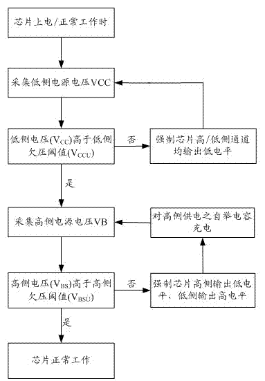
[0033] An undervoltage protection method for a high-voltage half-bridge driver chip, comprising the following steps:

[0034] S1) Power on the high-voltage half-bridge driver chip, so that the high-voltage half-bridge driver chip is in a working state,

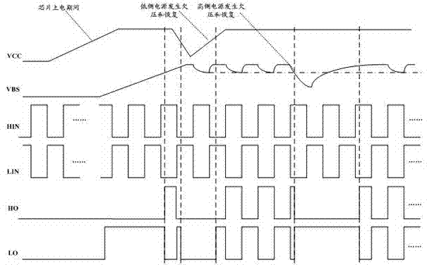
[0035] S2) Collect the low-side power supply voltage VCC. If the low-side power supply voltage VCC is lower than the set low-side undervoltage threshold, and the low-side undervoltage threshold is VCCU, the high-side channel and low-side channel of the high-voltage half-bridge are forced to drive the chip. All channels output zero level, thereby turning off the upper power transistor M1 and the lower power transistor M2 in the half bridge driven by the high-voltage half-bridge driver chip. If the low-side power supply voltage is higher than the low-side undervoltage threshold, the following one is performed: step;

[0036] S3) Collect the high-side power supply voltage VB, and compare the high-side power supply voltage and th...

Embodiment 2

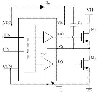
[0039] A high-voltage half-bridge circuit, comprising a high-voltage half-bridge drive circuit 1, the high-side output terminal HO and the low-side output terminal LO of the high-voltage half-bridge drive circuit 1 are respectively connected with an upper power tube M1 and a lower power tube M2, and the high-side The output terminal HO and the low-side output terminal LO are respectively connected to the gate terminals of the upper power transistor M1 and the lower power transistor M2, and the source terminal of the upper power transistor M1 and the drain terminal of the lower power transistor M2 are connected and connected to the high-voltage half-bridge drive circuit The high-side ground VS of 1 is connected, the drain terminal of the upper power transistor M1 is connected to the bus voltage VH, the source terminal of the lower power transistor M2 is connected to the low-side ground COM, and the low-side power supply terminal VCC of the high-voltage half-bridge drive circuit 1...


PUM


Abstract

The invention discloses an under-voltage protection method of a high-voltage half-bridge driving chip and a high-voltage half-bridge circuit. According to the method, when low-side power voltage VCC is lacking, an under-voltage protection circuit blocks high-end and low-end signal channels; if the low-side power voltage VCC is greater than a low-side under-voltage threshold VCCU and high-side power voltage VBS is smaller than a high-side under-voltage threshold VBSU, low level is forcedly output from a high-side channel of the high-voltage half-bridge driving chip, and high level is output from a low-side channel; an upper power tube is closed, and a lower power tube is opened, so the low-side power voltage VCC charges a bootstrap capacitor CB through an external diode until the high-side power voltage VBS is greater than the high-side under-voltage threshold VBSU; and the high-side power voltage and the low-side power voltage are greater than the high-side under-voltage threshold and the low-side under-voltage threshold, and the high-voltage half-bridge driving chip normally works. A circuit comprises the high-voltage half-bridge circuit, the upper power tube M1, the lower power tube M2, the diode DB and the bootstrap capacitor CB.

Description

technical field [0001] The invention relates to an undervoltage protection method for a high-voltage half-bridge drive chip and a high-voltage half-bridge circuit, which is specially aimed at the high-voltage half-bridge drive chip, and the chip is widely used in motor drive, high-power LED lighting, fluorescent lamp lighting, inverter power supply, etc. on the application system. Background technique [0002] The newly developed silicon-based and SOI (Silicon On Insulator)-based high-voltage and low-voltage compatible processes can integrate high-voltage power devices and reliable isolation technology, driving the rapid development of high-voltage power integrated circuits. It monolithically integrates high-voltage power devices with control and protection circuits, reduces the number of components, interconnections and solder joints in the system, not only improves the reliability and stability of the system, but also reduces the power consumption, volume, Weight and cost...

Claims


Application Information

Patent Timeline
Patent Type & Authority Applications(China)
IPC IPC(8): H02H7/20H02M1/08
Inventor 祝靖张允武张翠云钱钦松孙伟锋陆生礼时龙兴
Owner SOUTHEAST UNIV
Why Eureka
Try Eureka