Cutting Tool Holding Apparatus And Method Of Use

Inactive Publication Date: 2008-04-24
GROUND ASSAULT TOOLS
View PDF7 Cites 71 Cited by
  • Summary
  • Abstract
  • Description
  • Claims
  • Application Information

AI Technical Summary

Benefits of technology

[0040] As in the present invention, with high productivity, high horsepower machine applications wear is likely to be a problem on the leading front face of the base. Since it is intended that this component is not to be required to be replaced during the expected life of the road or mining machine, it is advantageous to have a sacrificial wear plate in front of the leading face that can easily be replaced if necessary.
[0041] Preferably, the sacrificial wear component has two legs that fit into two slots or ribs in the base when fitted. Wear will occur on the face and at some stage it will be necessary to replace only the component. Since wear rates of cutting tool holding apparatus are not consistent across the drums in such machines some may need replacing before others are worn out. To make a base with sufficient material as a sacrificial plate would add substantially to the cost. The base must be made of such a material as to be able to be welded to the drum and therefore a large amount of material would be required over the life of the machine. Furthermore, a small cast sacrificial wear compon

Problems solved by technology

It is inevitable that due to the severe environment accidental damage of known cutting tool holders and the cutting tools can occur before its normal expected lifetime.
As such, there are extensive costs in replacing the cutting holders and the secured tool that cut into the hardened surface due to wear and tear as work is conducted over a high number of revolutions.
In addition, the cutting tool holder may even detach completely and is not recoverable.
Accordingly, there can be severe wear and tear on each cutting tool holder during its operational life.
Though this may appear to be initially cost efficient in setting up costs, there are also continuous applied stresses and abrasion which often quickly damages the cutting tool holder.
A severe impact may fracture the weld and break off the tool holder.
The requirement to replace the tool holder may be difficult when on site as it lacks practicality and can be time consuming and expensive.
The cost in loss o

Method used


Image

  • Cutting Tool Holding Apparatus And Method Of Use
  • Cutting Tool Holding Apparatus And Method Of Use
  • Cutting Tool Holding Apparatus And Method Of Use

Examples


Example

DETAILED DESCRIPTION OF THE DRAWINGS

[0056] In addition terms such as “front”, “back”, “base”, “top”, “side”, “bottom”, “end”, “rear”, “underside” etc. refer to the orientation or configuration of a cutting tool holding apparatus when used according to the illustrations and to assist in indicating points of reference when viewing the accompanying figures. It is to be understood that these terms do not limit the present invention to any specific orientation or configuration of the invention.

[0057] In the specification the terms “comprising” and “containing” shall be understood to have a broad meaning similar to the term “including” and will be understood to imply the inclusion of a stated integer or step or group of integers or steps but not the exclusion of any other integer or step or group of integers or steps. This definition also applies to variations on the terms “comprising” and “containing” such as “comprise”, “comprises”, “contain” and “contains”.

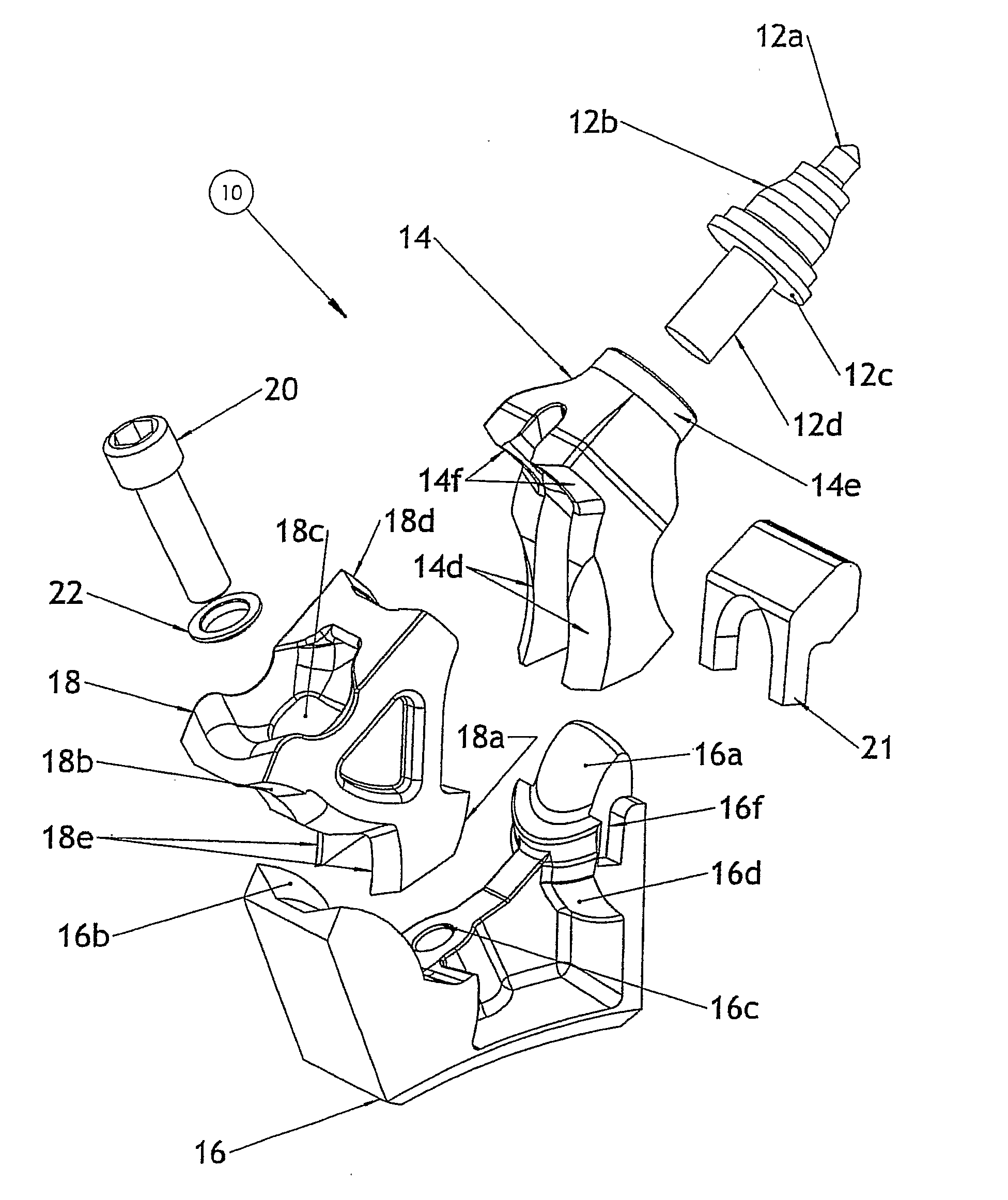
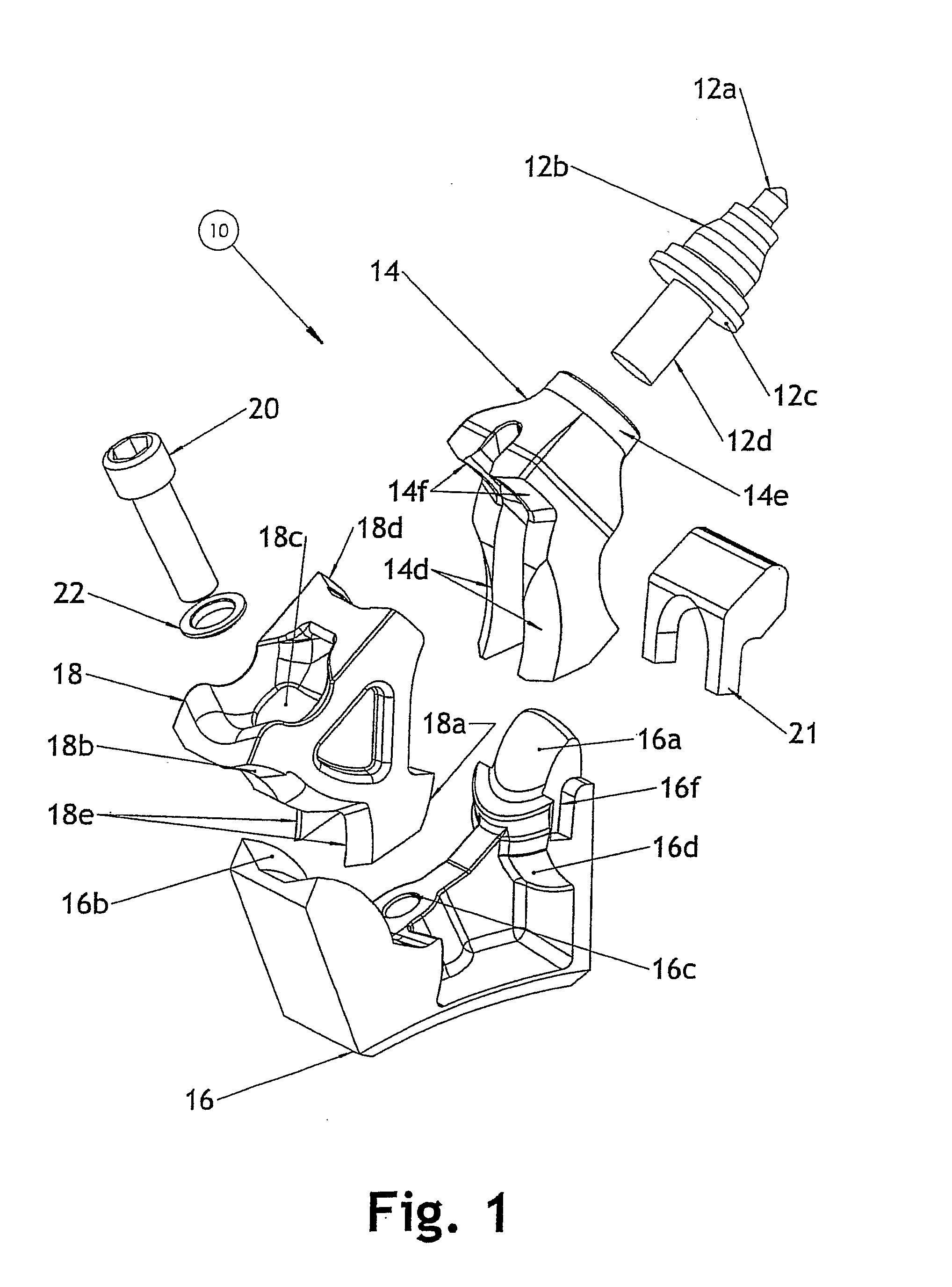
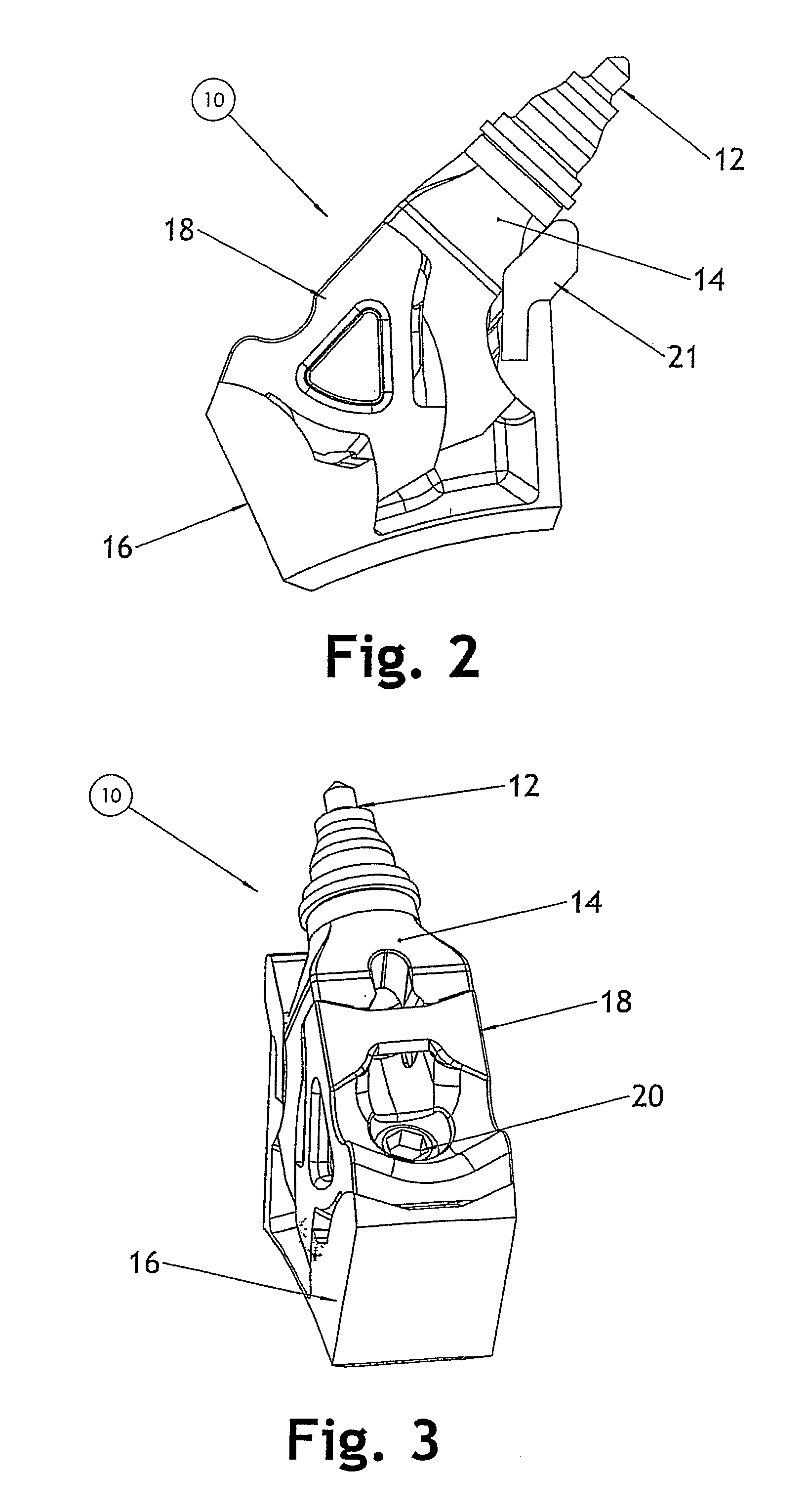
[0058]FIGS. 1-11 illustrat...


PUM


Abstract

A cutting tool holding apparatus (10), including in combination a cutting tool holder (14); a retainer (18) adapted to be positioned adjacent to the tool holder (14), the retainer including an aperture (18c), a base (16) including an aperture (16c) linked to the retainer aperture (18c), the base (16) adapted to support the holder (14) and the retainer (18), and a fastener (20) adapted to be inserted through the linked apertures, wherein securing the fastener in the linked apertures wedges the holder, retainer and base together and wherein at least two components of the tool holder, retainer and base contact via mating curved faces.

Description

FIELD OF THE INVENTION [0001] The invention relates to an apparatus for holding a cutting tool and methods of use thereof. In particular, the invention relates to apparatus for holding a cutting tool holder that is utilised on a ground engaging drum or wheel that excavates into the ground surface. BACKGROUND OF THE INVENTION [0002] There are a variety of road and mining machines that include a plurality of holders for securing cutting bits or teeth that assist in cutting into earth, asphalt, concrete or other hardened surfaces. Typically, these machines have a rotating drum, wheel or conveyor having a plurality of tool holders secured, generally by welding, cutting tools which are utilised to bite, cut, mill or trench into the hardened surface via the rotation of the drum, wheel or conveyor during operation. [0003] It is inevitable that due to the severe environment accidental damage of known cutting tool holders and the cutting tools can occur before its normal expected lifetime. A...

Claims


Application Information

Patent Timeline
IPC IPC(8): E21C35/193
CPCE21C2035/191E21C35/19E21C35/191
Inventor WILLOUGHBY, JOHN MICHAEL
Owner GROUND ASSAULT TOOLS
Why Eureka
Try Eureka