Communication quality management and apparatus

a communication quality and management method technology, applied in electrical devices, digital transmission, data switching networks, etc., can solve the problems of difficult to guarantee the confirmation and quality of the reception status at each reception terminal, and the difficulty of applying streaming unicast to a large-scale servi

Inactive Publication Date: 2008-04-24
NEC CORP
View PDF19 Cites 74 Cited by
  • Summary
  • Abstract
  • Description
  • Claims
  • Application Information

AI Technical Summary

Benefits of technology

[0012]The communication quality management method and apparatus of the present invention can attain the following practically typical effects. That is, the method and apparatus can acquire the quality information in data distribution using a multicast. The method and apparatus ca

Problems solved by technology

It is difficult to apply streaming unicast to a large-scale service.
It is difficult t

Method used


Image

  • Communication quality management and apparatus
  • Communication quality management and apparatus
  • Communication quality management and apparatus

Examples


first embodiment

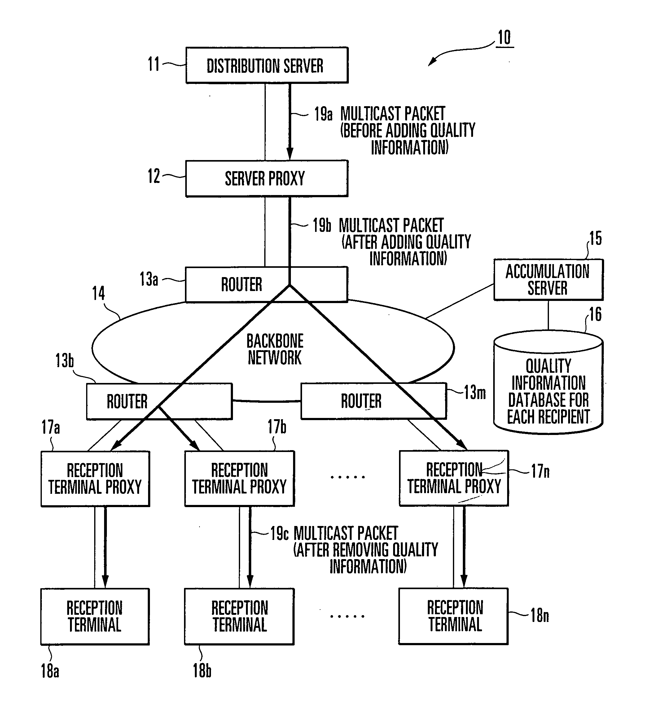
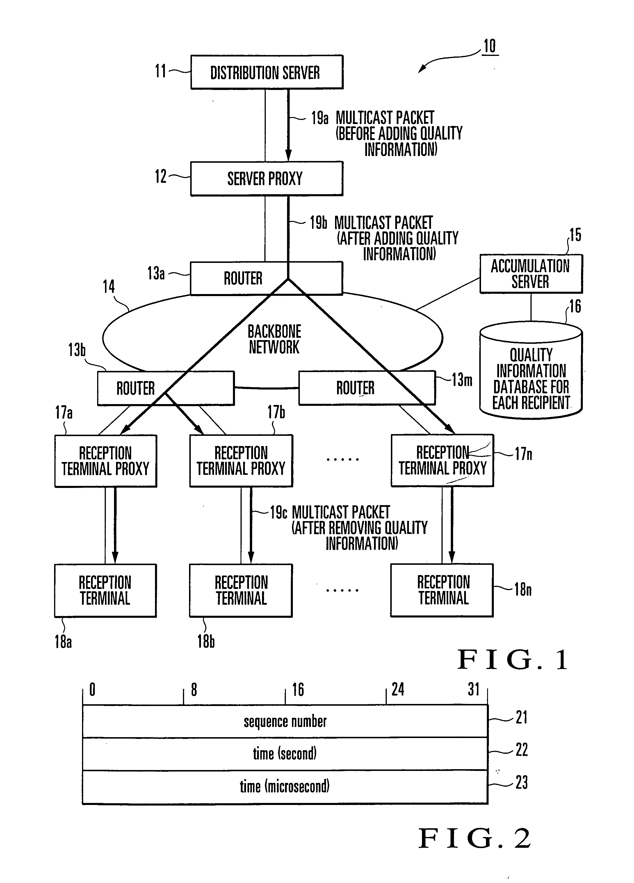
[0023]A communication quality management apparatus according to the first embodiment of the present invention will be described with reference to FIG. 1.

[0024]As shown in FIG. 1, a communication quality management apparatus 10 comprises a distribution server 11, a server proxy 12, a plurality of routers 13a to 13m connected to a backbone network 14 serving as a network such as the Internet, reception terminal proxies 17a to 17n, a plurality of reception terminals 18a to 18n, an accumulation server 15 connected to the backbone network 14, and a quality information database 16 connected to the accumulation server 15.

[0025]As can be apparent from the comparison with the conventional multicast distribution system 70 described above, the communication quality management apparatus 10 of the present invention includes the server proxy 12 located under the distribution server 11, i.e., between the distribution server 11 and the router 13a.

[0026]The reception terminal proxies 17a to 17n are...

second embodiment

[0039]A communication quality management apparatus according to the second embodiment of the present invention will be described with reference to FIG. 6. The same constituent elements of the first embodiment are denoted by the same reference numerals for the descriptive convenience. A communication quality management apparatus 60 shown in FIG. 6 comprises a distribution server 11, server proxy 12, a plurality of routers 13a to 13m, a plurality of reception terminal proxies 17, a plurality of reception terminals 18, accumulation server 15, and quality management server 20. That is, as can be apparent from the comparison with FIG. 5 described above, the apparatus of the second embodiment is different from that of the first embodiment in that the quality management server 20 is arranged in place of the quality information database 16 for each recipient of the first embodiment in FIG. 5.

[0040]The operation of the communication quality management apparatus 60 according to the second emb...


PUM


Abstract

A server proxy (12), which is arranged between a distribution server (11) and a router (13a), adds quality information to a packet (19a) from the distribution server (11) to output a packet (19b). A plurality of reception terminal proxies (17a-17n), which are arranged immediately before respective reception terminals (18a-18n), remove the quality information from the packet (19b) distributed via a network (14) and routers (13b-13m), and distribute only necessary information to the respective reception terminals (18). Each reception terminal proxy (17) which includes a quality information acquisition unit (17A) acquires the quality information to transmit, from a quality information calculation/transmission unit (17B), the quality information (51) to an accumulation server (15). The accumulation server (15) saves, in a quality information database, packet quality information (52) for each reception terminal (18).

Description

TECHNICAL FIELD[0001]The present invention relates to a communication quality management method and apparatus and, more particularly, to a communication quality management method and apparatus when simultaneously multicasting data in the form of multicast packets from a distribution server to a plurality of reception terminals via a network such as the Internet.BACKGROUND ART[0002]A variety of services are provided via a network due to the widespread use of a broadband network. Among these services, a streaming distribution service represented by a sport relay broadcasting is available. Streaming is not playback upon completion of downloading files of audio and video data via the Internet or the like, but playback while downloading the files.[0003]Unicast of streaming data (one-to-one communication form which designates only one message destination address) requires user count-dependent resources such as a distribution server load and network band. It is difficult to apply streaming...

Claims


Application Information

Patent Timeline
IPC IPC(8): H04L12/56
CPCH04L41/5003H04L47/24H04L47/15H04L47/10
Inventor SUZUKI, KAZUYAJIBIKI, MASAHIRO
Owner NEC CORP
Why Eureka
Try Eureka