Structure of mechanical arm transmission structure

Inactive Publication Date: 2008-04-24
CHANG SHU MAN
View PDF2 Cites 6 Cited by
  • Summary
  • Abstract
  • Description
  • Claims
  • Application Information

AI Technical Summary

Benefits of technology

[0009]The present invention has been accomplished under the circumstances in view. It is the main object of the present invention to provide a mechanical arm transmission s

Problems solved by technology

1. The transmission belt 80 is suspending above the rectilinear base 60 and exposed to the outside, external bodies may fall to the top wall of the lower part 80b of the transmission belt 80 and carried by the lower part 80b of the transmission belt 80 to the driven belt wheel 82 to rub against the driven belt wheel 82, causing disconnection of the transmission belt 80 from the driven belt wheel 82. Furth

Method used


Image

  • Structure of mechanical arm transmission structure
  • Structure of mechanical arm transmission structure
  • Structure of mechanical arm transmission structure

Examples


Embodiment Construction

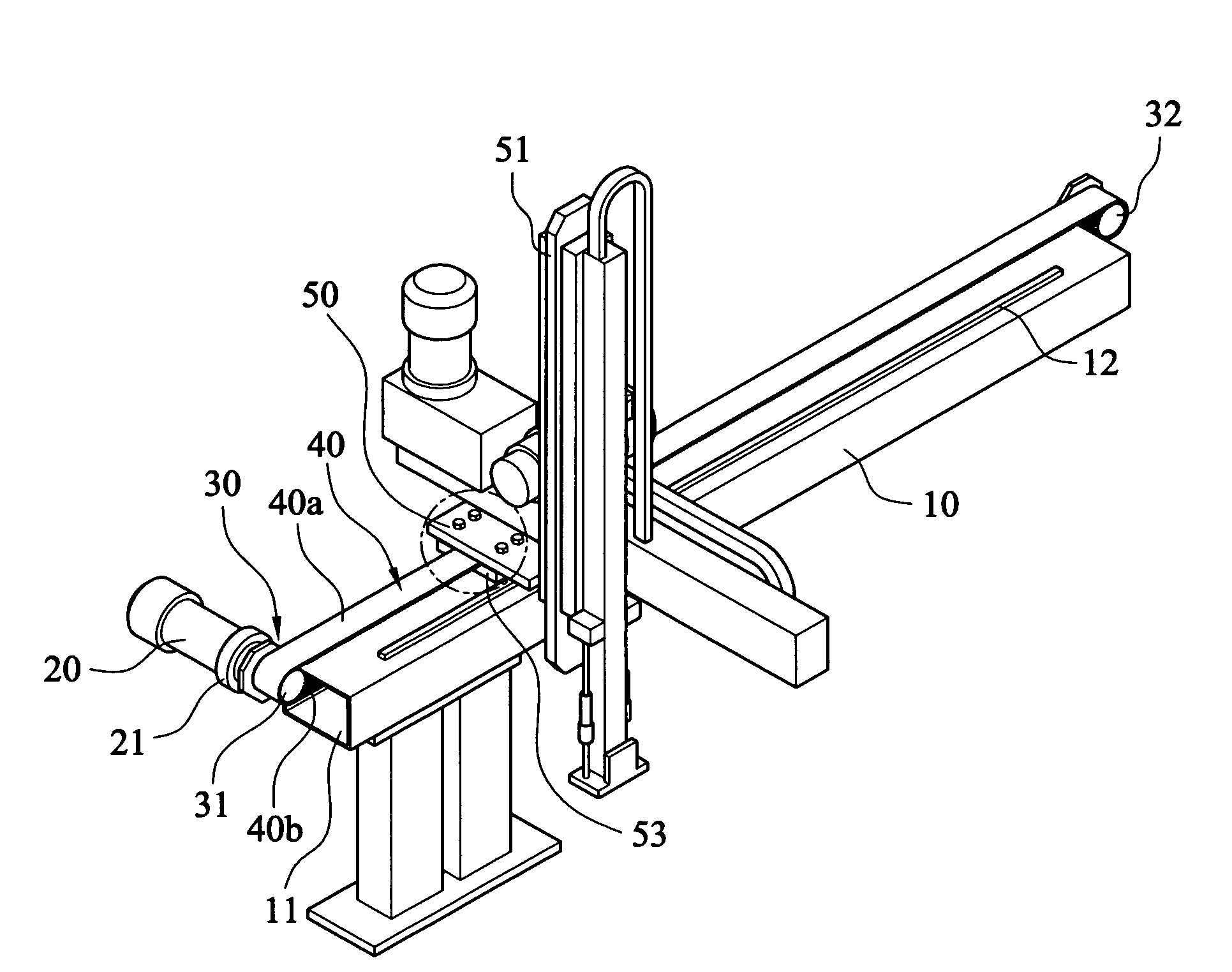
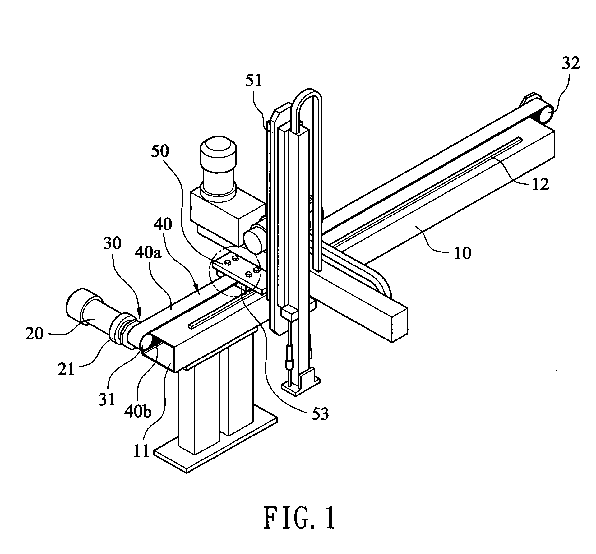
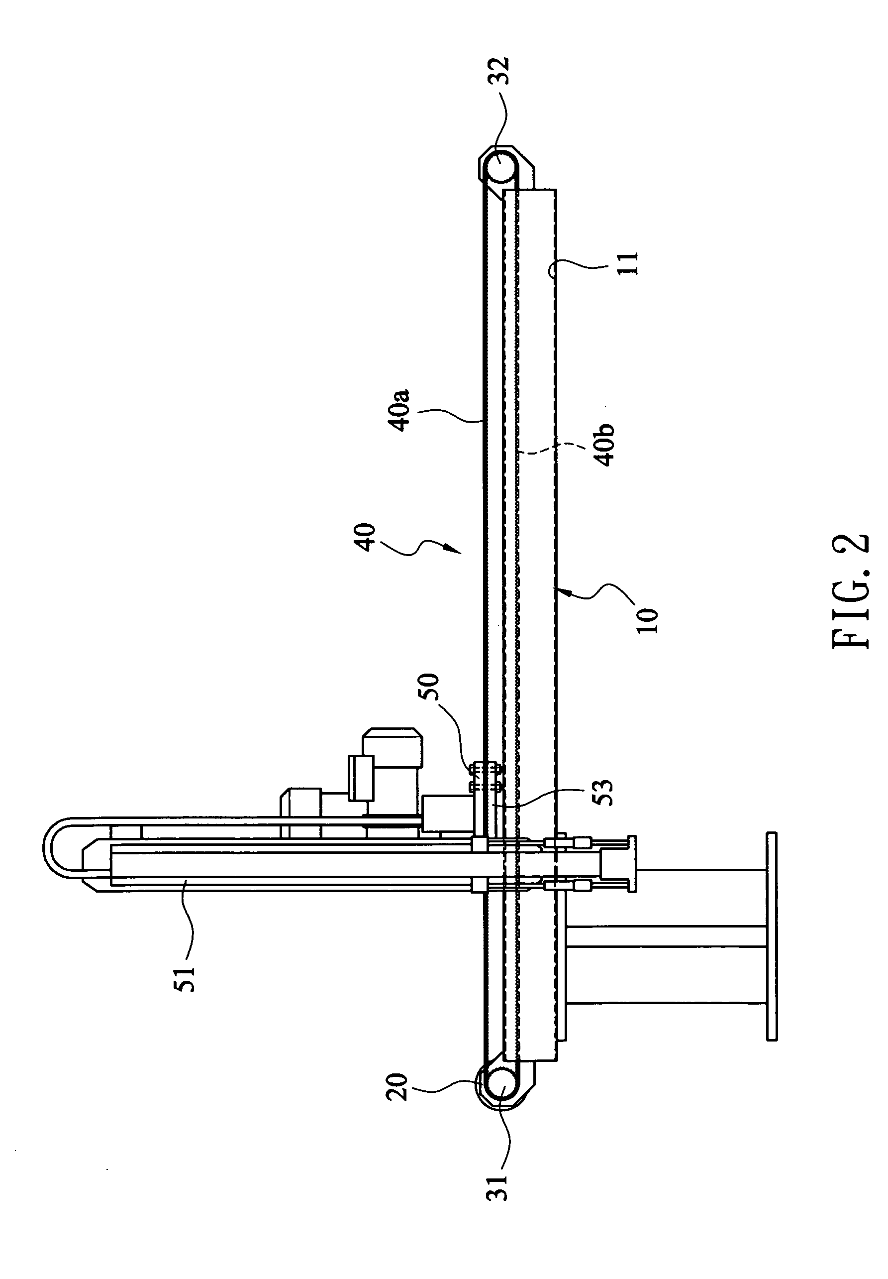
[0019]Referring to FIGS. 1˜3, a mechanical arm transmission structure in accordance with the present invention is shown comprised of a horizontal base 10, a motor 20, a transmission mechanism 30, and a slide 50.

[0020]The horizontal base 10 is a rectangular tube having a longitudinal receiving space 11 extending to through two distal ends thereof and a pair of longitudinal sliding rails 12 arranged in parallel on the top side thereof.

[0021]The motor 20 is fixedly fastened to one end of the horizontal base 10 corresponding to the open side of the longitudinal receiving space 11, adapted to rotate the transmission mechanism 30 through a speed reducer 21 (i.e., the motor 20 has a speed reducer coupled to the output shaft thereof).

[0022]The transmission mechanism 30 comprises a drive belt wheel 31 coupled to the speed reducer 21 for rotation by the motor 20, a driven belt wheel 32, and a transmission belt 40. The drive belt wheel 31 and the driven belt wheel 32 are respectively pivotally...


PUM


Abstract

A mechanical arm transmission structure includes a tubular horizontal base, a drive belt wheel and a driven belt wheel mounted inside the horizontal base, a transmission belt mounted on the drive belt wheel and the driven belt wheel with the upper part thereof suspending above the horizontal base, a motor mounted outside the horizontal base for rotating the drive belt wheel through a speed reducer, a slide movable with the transmission belt along longitudinal rails at the top of the horizontal base and carrying a mechanical arm, and a holding down block fastened to the bottom side of the slide to affix the slide to the upper part of the transmission belt for allowing movement of the slide with the transmission belt along the longitudinal rails.

Description

BACKGROUND OF THE INVENTION[0001]1. Field of the Invention[0002]The present invention relates generally to mechanical arms and more specifically, to a mechanical arm transmission structure, which has the lower part of the transmission belt to be received in the hollow horizontal base and uses a toothed engagement structure to secure the slide carrying the mechanical arm to the transmission belt for positive transmission.[0003]2. Description of the Related Art[0004]Nowadays, mechanical arms are intensively used for different industrial applications. The invention pertains to an improvement on the arrangement of a mechanical arm transmission structure.[0005]FIGS. 5˜7 show a mechanical arm transmission structure according to the prior art. According to this design, the mechanical arm transmission structure comprises a rectilinear base 60, which has two longitudinal rails 61 arranged in parallel on the top, and a slide 70 coupled to and movable along the longitudinal rails 61. The slide...

Claims


Application Information

Patent Timeline
IPC IPC(8): F16H61/00
CPCB25J9/041F16H19/06B25J9/104
Inventor CHANG, SHU MAN
Owner CHANG SHU MAN
Why Eureka
Try Eureka