Method, System and a Computer Program Product for Condition Monitoring of a Continuous Element Moving in a Fiber Web or Paper Finishing Machine

a technology of continuous element and condition monitoring, which is applied in the field of condition monitoring of continuous element moving in a fiber web or paper finishing machine, can solve the problems of denying user access to dangerous places, unable to gain access to profile monitoring by many machines, and operator knocking a roll is in danger, so as to improve safety at work, easy and quick observation, and simple implementation

Active Publication Date: 2019-02-14
VALMET TECH OY
View PDF0 Cites 2 Cited by
  • Summary
  • Abstract
  • Description
  • Claims
  • Application Information

AI Technical Summary

Benefits of technology

[0015]In the method, the fabric is installed in a fabric run, wherein it moves via a machine element equipped with a sensor assembly, a reference profile is formed for the tension profile of the fabric formed between the rotating machine element and the fabric after installing the fabric in the fabric run, the tension profile, formed from the measurement signal, of the fabric formed between the machine element and the fabric and the reference profile are compared, and information is produced from this comparison for monitoring the condition of the fabric. The comparison provides information about the condition and quality of the fabric. Owing to the formed reference profile, it is possible to identify a change in the fabric condition already at an early stage, monitor its development, make the condition change and the related information available for the machine control system or known to the operator, and perform actions regarding the fabric. Thus, the invention also improves safety at work. Owing to the reference profile and the comparison made relative thereto, it is possible to determine the condition of the fabric without the operator having to go near it in order to take manual measurements. Furthermore, the invention enables easy and quick observation of the response caused to the fabric condition and quality by the actions taken.
[0016]According to an embodiment, the sensor assembly, with which the cross-directional profiles of force or pressure are formed, may include one or more sensors installed on the shell and / or the cover of the machine element. The sensor may measure force or pressure directly or indirectly. Owing to the sensor assembly, the fabric condition can be monitored even with measurement arrangements that already exist in the machine element, this taking place surprisingly by utilizing a cross-directional profile measurement of the nip between the machine element and the fabric, for example. In other words, with the invention it is possible to diversify the purpose of use of an existing sensor assembly in a surprising way without major installation or modification work. If the machine element is already equipped with a sensor assembly for measuring the cross-directional profile of nip force of a nip, for example, the method according to the invention can even be a merely program-based implementation in the machine control automation. In this case, it is very simple to implement.

Problems solved by technology

In practice, this leads to the necessity of denying user access to dangerous places.
Due to the aforementioned reasons, it is impossible for operators in many machines to gain access to profile monitoring in the wind-up section, which is an essential part of machine monitoring.
The introduction of these safety improvements is grounded, since, when a web break occurs, an operator knocking a roll is in danger.
In such a situation, an operator feeling the surface of a parent roll will certainly get hurt and the risk of death is significant.
In this case, it is already late for any improving actions, as the roll is already completed.
At this stage, nothing can any longer be done to improve its tightness or other properties.
Furthermore, the measuring of even stopped parent rolls begins to be challenging today for safety reasons.
In addition, it is difficult to enter the winder's unwinder or the preceding reel spool storage rails because of safety gates, for example.
In some mills (particularly in North America), access to the dry end side of the winder is also restricted.
However, this publication does not propose a method for condition monitoring of a target element; instead, monitoring of both the fabric condition / wear and the roll quality / hardness have practically been implemented with the aforementioned manual methods.
This poses a problem to operators, since it should be possible to monitor fabric wear even under conditions other than during a shutdown.

Method used


Image

  • Method, System and a Computer Program Product for Condition Monitoring of a Continuous Element Moving in a Fiber Web or Paper Finishing Machine
  • Method, System and a Computer Program Product for Condition Monitoring of a Continuous Element Moving in a Fiber Web or Paper Finishing Machine
  • Method, System and a Computer Program Product for Condition Monitoring of a Continuous Element Moving in a Fiber Web or Paper Finishing Machine

Examples


Embodiment Construction

[0027]Referring more particularly to FIGS. 1-8:

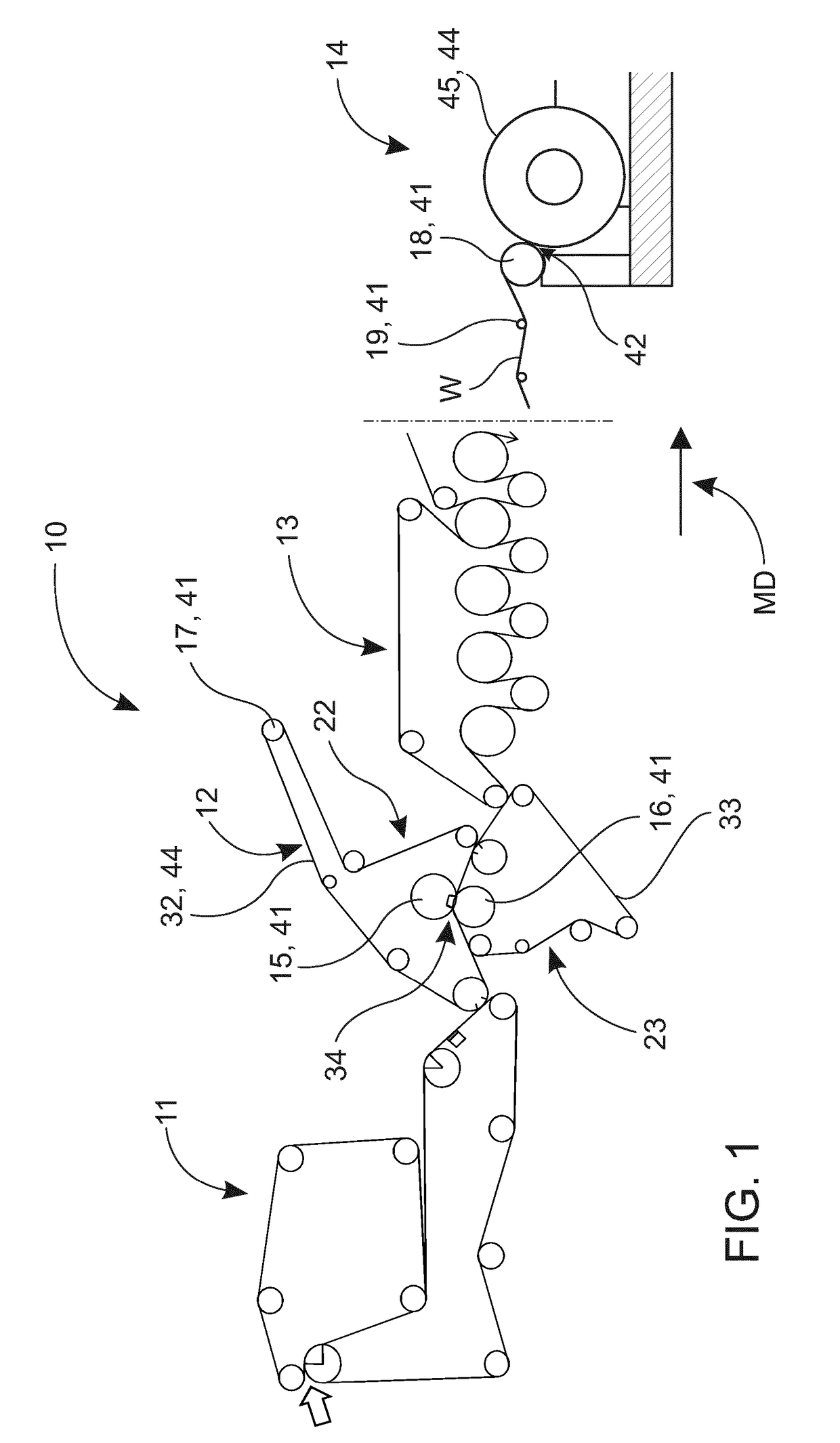
[0028]FIG. 1 is a rough diagrammatic view of one example of an embodiment of the invention, which in this case is a fiber web machine 10. In addition to a fiber web machine, the invention can also be utilized in a paper finishing machine, for example. Some examples of these may include slitting, calendering, coating, surface sizing and rewinding. A fiber web or paper finishing machine includes one or more sub-entities 11-14. A fiber web machine may include the following as subsequent sub-entities (FIG. 1 from left) located in the web travel direction, i.e. in the machine direction: headbox (not shown), web forming section 11, press section 12, dryer section 13, one or more possible finishing devices (not shown), and reel 14. A finishing device may be an integral part of the machine line (online) or a separate sub-entity of its own (offline). Other components may of course exist between parts 11-14. Thus, the order set forth is not inten...


PUM

PropertyMeasurementUnit
angle of rotationaaaaaaaaaa
forceaaaaaaaaaa

Abstract

The invention relates to a method for monitoring the condition of a continuous element (44) moving in a fiber web or paper finishing machine, said monitoring being performed with a rotating machine element (41), which is equipped with a sensor assembly (24) that measures force or pressure and against which the continuous element moves. In the method, the machine element is made to rotate against the continuous element, a measurement signal (25) is generated between the machine element and the continuous element with the sensor assembly, and a cross-directional profile (21) of force or pressure generated between the machine element and the continuous element is formed from the measurement signal. Said moving continuous element is a fabric (32, 33) installed in a fabric run (22, 23) traveling via the machine element. In the method, the fabric is additionally installed in a fabric run, wherein it moves via said machine element equipped with a sensor assembly, a reference profile (35) is formed for the cross-directional profile after installing the fabric in the fabric run, the cross-directional profile formed from the measurement signal and representing force or pressure generated between the machine element and the fabric is compared with the reference profile, and information (37) is produced from the comparison for monitoring the condition of the fabric. The invention also relates to a corresponding system and a computer program product.

Description

CROSS REFERENCES TO RELATED APPLICATIONS[0001]This application is a U.S. national phase of PCT / FI2017 / 050121 filed on Feb. 24, 2017 and claims priority on FI 20165145 filed on Feb. 25, 2016, both of which are incorporated herein by referenceSTATEMENT AS TO RIGHTS TO INVENTIONS MADE UNDER FEDERALLY SPONSORED RESEARCH AND DEVELOPMENT[0002]Not applicable.BACKGROUND OF THE INVENTION[0003]The invention relates to a method for monitoring the condition of a continuous element moving in a fiber web or paper finishing machine, said monitoring being performed with a rotating machine element, which is equipped with a sensor assembly that measures force or pressure and against which the continuous element moves, and wherein[0004]the machine element is made to rotate against the continuous element,[0005]a measurement signal is generated between the machine element and the continuous element with the sensor assembly,[0006]a cross-directional profile of force or pressure generated between the mach...

Claims


Application Information

Patent Timeline
Patent Type & Authority Applications(United States)
IPC IPC(8): D21G9/00G01L5/10B65H18/26
CPCD21G9/0036G01L5/108B65H18/26B65H2515/314B65H2801/84B65H23/044B65H23/188B65H26/04D21G9/0054G01L5/0085G01L5/045
Inventor KETTUNEN, HEIKKIKRAMER, GERALDPITKANEN, TATUSIPPRELL, JAMESVANDENHEUVEL, TODD
Owner VALMET TECH OY
Why Eureka
Try Eureka