Catheter tunneler adapter and methods of assembly to a catheter and use

Active Publication Date: 2008-04-24
MEDICAL COMPONENTS INC
View PDF23 Cites 68 Cited by
  • Summary
  • Abstract
  • Description
  • Claims
  • Application Information

AI Technical Summary

Benefits of technology

[0009]The present invention is an adapter that at its distal end is securable onto the ends of two (or more) lumens of a catheter to facilitate implantation thereof in a patient's vasculature, and is securable at its proximal end to, sequentially, a stylet and also a tunneler, so that while connected to the catheter's proximal end it permits releasable connection with a stylet for the guide wire to permit implantation of the distal portion in place in the vasculature, and then with a tunneler for subcutaneous tunneling of the proximal portion of the catheter. The adapter includes a body defining a through passageway from its proximal end to its distal end. The through passageway permits a stylet to b

Problems solved by technology

However, this technique is only possible in cases where the catheter is of a relatively small diameter, made of a stiff material, and not significantly larger than the guide wire.
For some catheters, th

Method used


Image

  • Catheter tunneler adapter and methods of assembly to a catheter and use
  • Catheter tunneler adapter and methods of assembly to a catheter and use
  • Catheter tunneler adapter and methods of assembly to a catheter and use

Examples


first embodiment

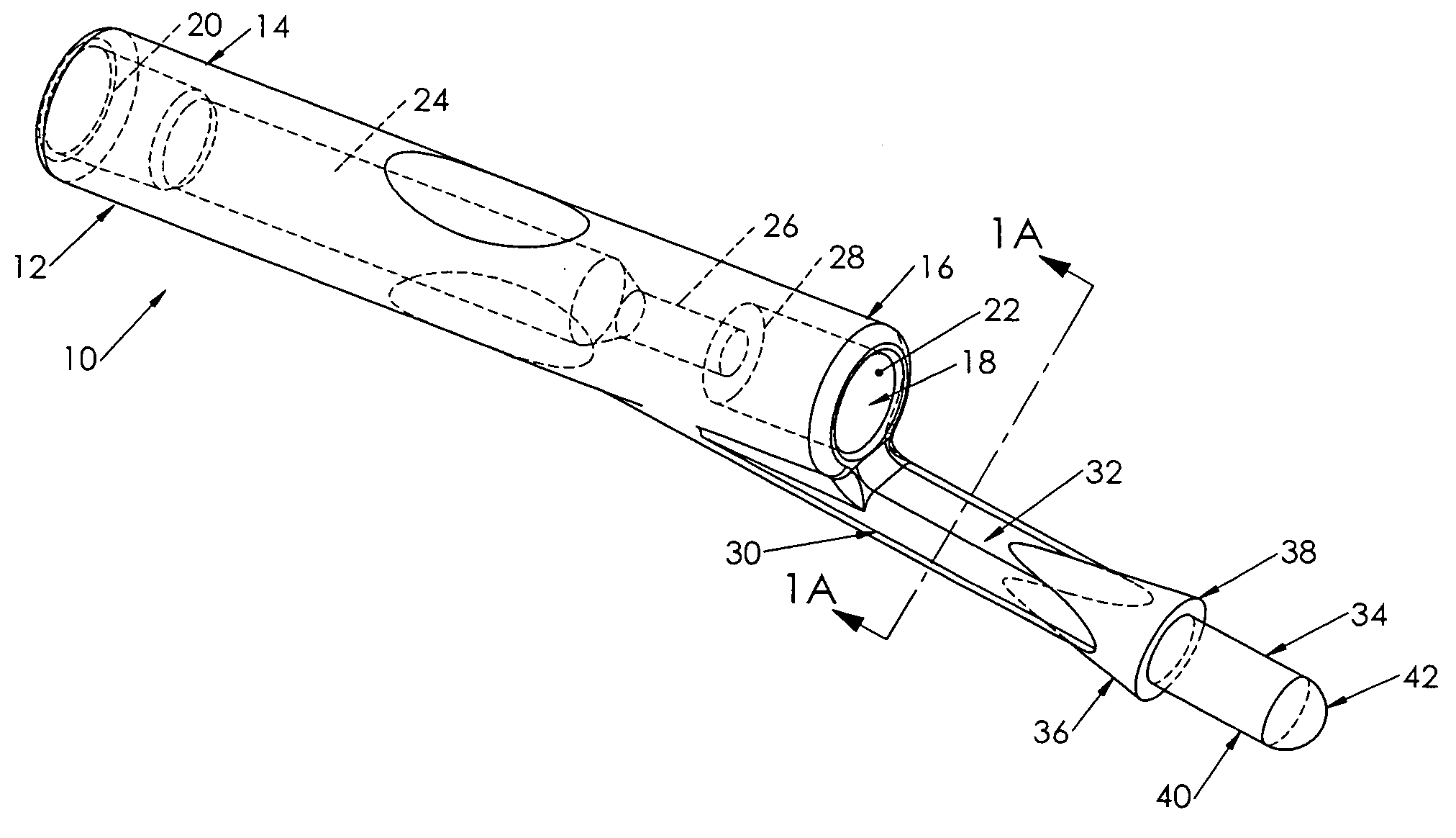
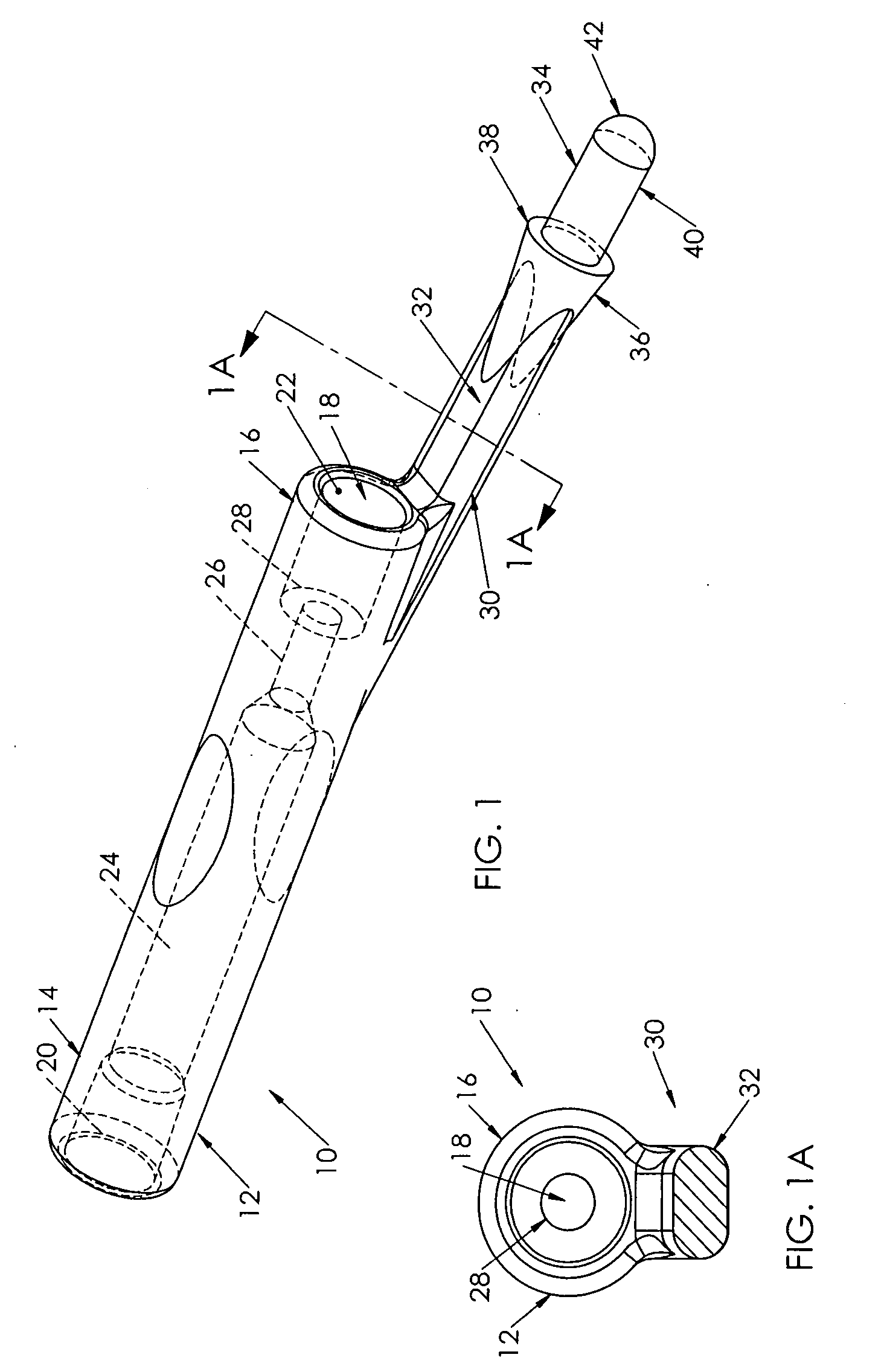
[0027]adapter 10 of the present invention is shown in FIGS. 1 to 7. Adapter 10 is shown in FIG. 1 to include body 12 having a proximal end 14, a distal end 16, a through passageway 18 extending through the body 12 from an entrance 20 at the proximal end 14 to an exit 22 at the distal end 16. The through passageway 18 also includes an intermediate, smaller diameter portion 24 and a transition portion 26 extending to the exit 22 and defining a distally facing ledge 28.

[0028]Adapter 10 also includes a flexible arm 30 having an elongated section, strut or tether 32 extending to a free end 34 having a frustoconical enlargement 36 defining a distally facing ledge 38 distally from which extends a somewhat elongated plug 40 having a rounded, blunt tip 42. Preferably, the strut or tether 32 has a flattened cross-section (see FIG. 1A) facilitating deflection of the flexible arm toward the longitudinal axis defined by the through passageway 18, as will be described hereinbelow relating to subc...

third embodiment

[0037]adapter 300 is depicted in FIG. 9. Adapter 300 is modified at its distal end to accommodate a catheter 350 whose first and second lumens 360,362 have a D-shaped cross-section. Adapter passageway 318 has an exit 322 that is D-shaped in cross-section. Also, plug 340 on flexible arm 330 also has a D-shaped cross-section to be received sealingly into the second lumen's proximal end, and a correspondingly shaped enlargement 336.

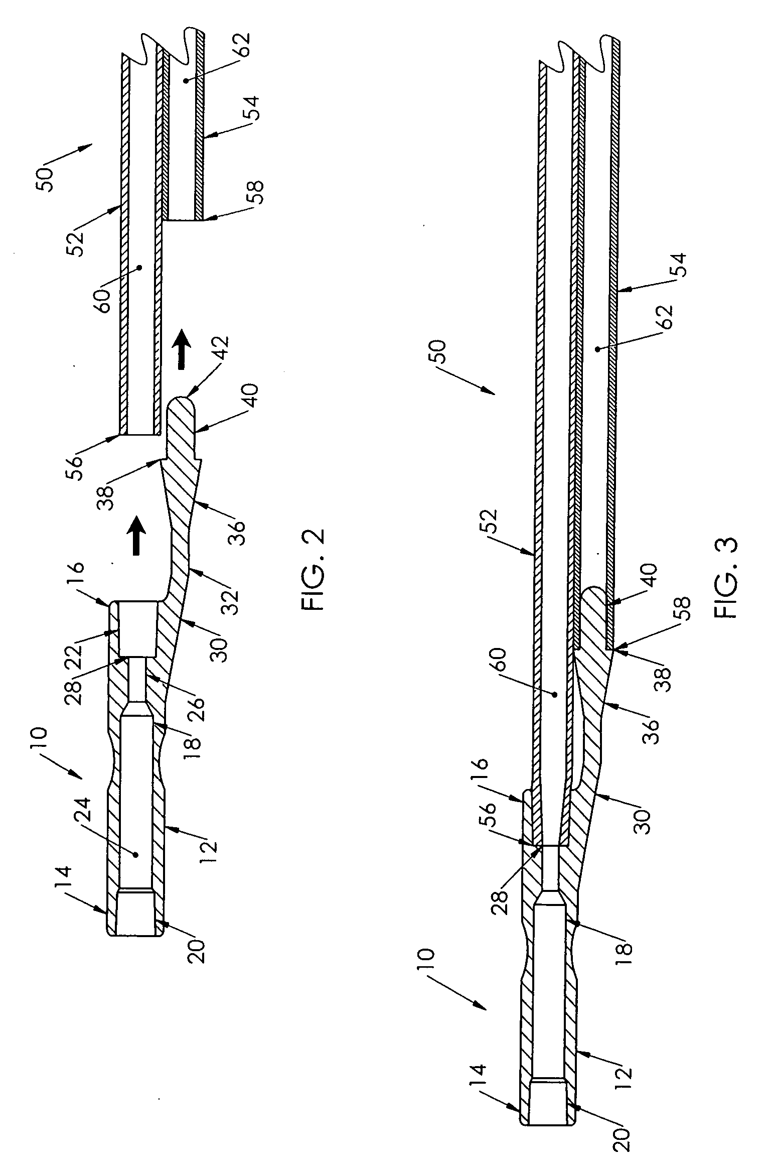
[0038]A flow chart is provided in FIG. 10 to set forth the method of using the adapter of the present invention, based on the embodiment of adapter 10 shown in FIGS. 1 to 3, and following a retrograde tunneling procedure. It is expected that the adapter of the present invention will be affixed to the proximal tubes 52,54 of the catheter 50 when received by the practitioner, and a stylet 70 is in position in the assembly releasably connected to the adapter 10. When received as an assembly by the practitioner, the assembly may either be inserted in the vascula...


PUM


Abstract

A catheter tunneling adapter (10) including a generally elongated body (12) having a proximal end (14), a distal end (16) and a through passageway (18) extending therethrough between the proximal and distal end. The proximal end (14) of the adapter (10) is connectable both to a proximal hub of a stylet (70) and subsequently to the distal end (84,94) of a tunneler (80,90). The distal end (16) of the adapter (10) comprises a connector for connecting a plurality of proximal catheter tubes (52,54) thereto, wherein the proximal end of one tube (52) is affixed within the passageway at the adapter's distal end (16) and the proximal end of the second tube (54) is plugged by a plug (40) extending distally from a free end of an elongate flexible arm (30) that also extends distally of the adapter's distal end (16), such that the plug is offset laterally therefrom. The flexible arm (30) and the affixed second tube end (58) are deflectable toward the first tube (52) to reduce the profile of the assembly during tunneling. Methods of affixing an adapter to a catheter, of inserting a catheter into a patient, and of subcutaneously tunneling a catheter under a patient's skin using the tunneling device, are also disclosed.

Description

CROSS REFERENCE TO RELATED APPLICATIONS[0001]This application claims priority from Provisional U.S. Patent Application Ser. No. 60 / 852,847 filed Oct. 19, 2006.FIELD OF THE INVENTION[0002]The present invention relates to medical devices and more particularly to an adapter for a vascular catheter to facilitate subcutaneous tunneling thereof.BACKGROUND OF THE INVENTION[0003]Catheters for the introduction or removal of fluids may be located in various venous locations and cavities throughout the body of a patient for introduction of fluids to the body or removal of fluids from the body. Such catheterization may be performed by using a single catheter having multiple lumens. A typical example of a multiple lumen catheter is a dual lumen catheter in which one lumen introduces fluid and the other lumen removes fluid. An example of such a multiple catheter is the SPLIT-CATH® catheter, sold by Medical Components, Inc. of Harleysville, Pa.[0004]Generally, to insert any catheter into a blood v...

Claims


Application Information

Patent Timeline
IPC IPC(8): A61M39/00
CPCA61B17/3415A61B2017/320056A61M25/0102A61M25/0194A61M2039/1077A61M39/105A61M2025/0034A61M2025/0037A61M39/10
Inventor STEPHENS, JOHN
Owner MEDICAL COMPONENTS INC
Why Eureka
Try Eureka