

Device and method for vascular closure
a delivery system and vascular technology, applied in the field of vascular closure delivery system, can solve the problems of reducing the benefits of using smaller or less invasive percutaneous injection, and reducing the use of vascular closure devices
- Summary
- Abstract
- Description
- Claims
- Application Information
AI Technical Summary
Problems solved by technology
Method used
Image

Examples
Embodiment Construction
[0049]A vascular closure delivery system that may be used to deliver needles and sutures for closing internal tissue walls after a medical procedure is performed through a vascular wall opening is provided. Tissue that may be closed in accordance with the teachings herein may be part of a lumen such as a blood vessel, body cavity, other organ, or any tissue suitable for suturing.
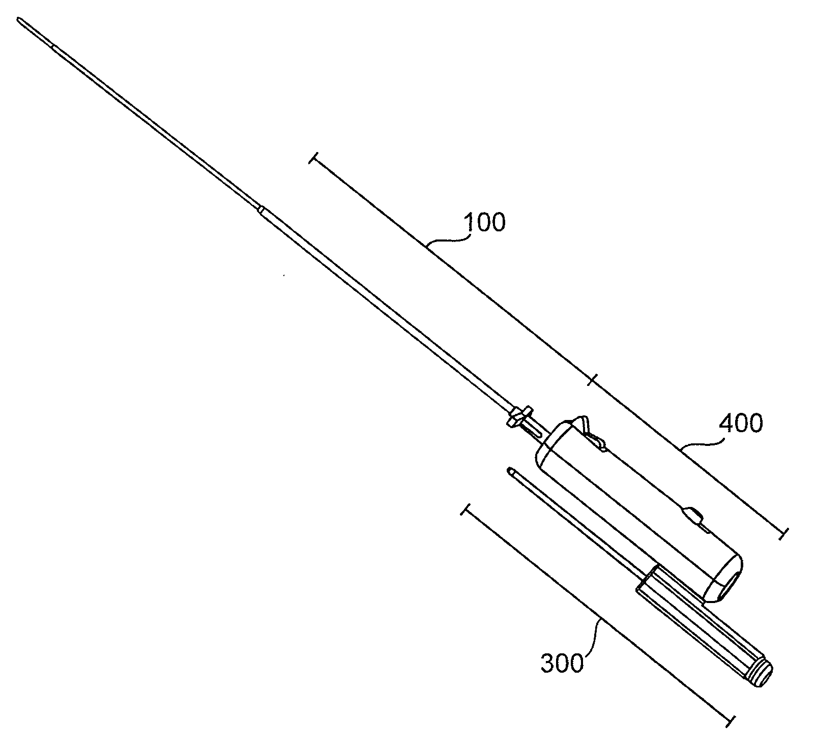
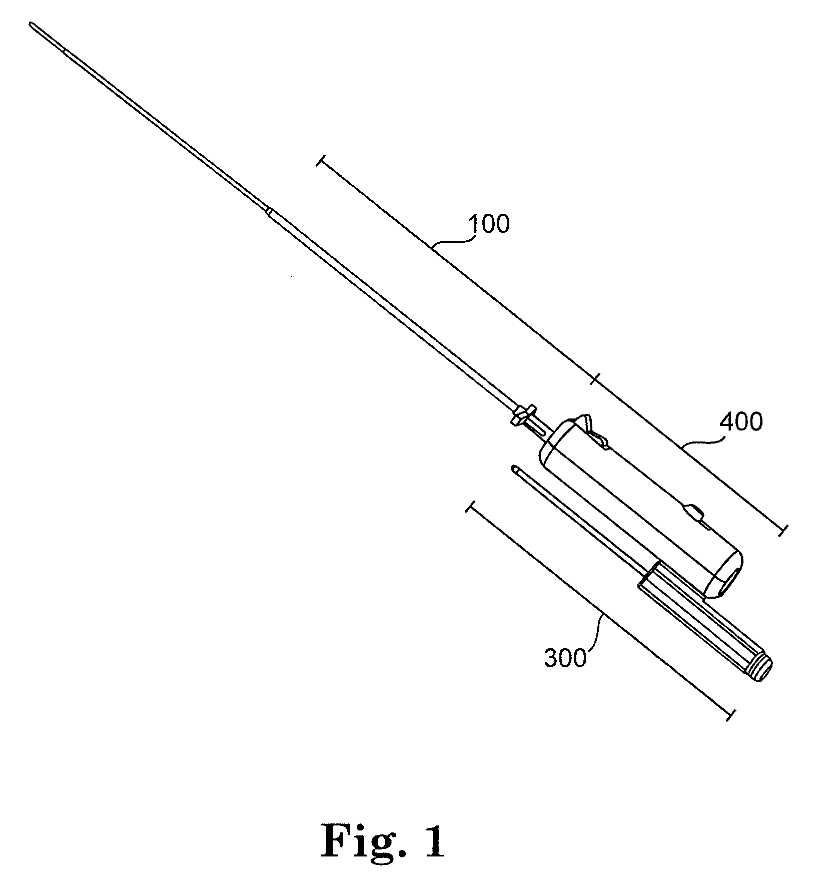
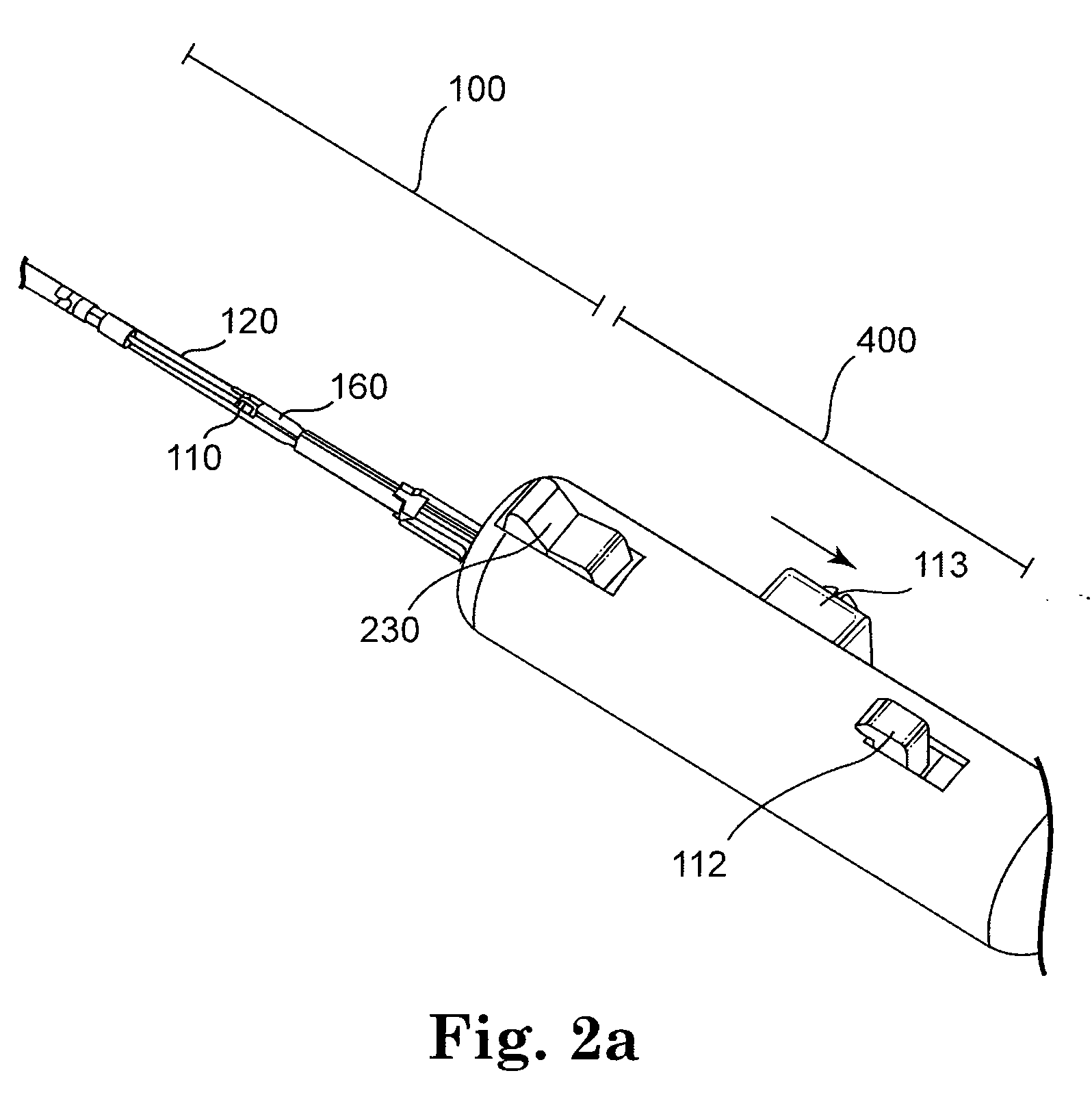
[0050]FIG. 1 illustrates one embodiment of the vascular closure delivery system. As shown, the vascular closure delivery system may include a handle 400, a needle and suture delivery unit 100, and a suture knot system 300. FIGS. 2a-2d illustrate one embodiment of a vascular closure delivery system comprising a handle and needle and suture delivery unit 100. FIG. 2a illustrates the needle and suture delivery unit in a closed configuration, FIGS. 2b and 2c illustrates the needle and suture delivery unit in a partially open and an open configuration, respectively, and FIG. 2d illustrates the needle and suture d...
PUM
 Abstract
Description
Claims
Application Information