
Vascular closure

a technology of vascular closure and aperture, which is applied in the field of methods and apparatus for closing apertures, can solve the problems of increasing the time for surgical procedures as well as the overall cost of procedures, affecting the safety of patients, so as to achieve the effect of improving patient safety, overcoming disadvantages, and high sensitivity to the location of the apparatus

Inactive Publication Date: 2010-02-16
REX MEDICAL LP
View PDF143 Cites 55 Cited by
  • Summary
  • Abstract
  • Description
  • Claims
  • Application Information

AI Technical Summary

Benefits of technology

"The present invention provides a clip apparatus for closing a lumen aperture, particularly a vascular aperture, resulting from the insertion of a surgical implement. The clip apparatus includes an elongated strand with a central portion and extremity portions extending from the central portion. The clip apparatus has memory characteristics that cause the extremity portions to curl towards and over one another when the strand is in an unconstrained disposition, free of externally applied stress. The clip apparatus may be used in a two-stage operation where the clip is first partially deployed and then fully deployed. The clip apparatus may also include a band to retain the clip in a closed position. The invention provides a closed clip apparatus that is easier to use, safer, and more effective in closing a lumen aperture than previous clips."

Problems solved by technology

This is quite difficult not only because of the high blood flow from the artery, but also because there are many layers of tissue that must be penetrated to reach the femoral artery.
This increases time for the surgical procedure as well as overall cost of the procedure since the hospital staff must physically hold pressure and the patient's discharge is delayed because of the inability to ambulate.
This is not an efficient use of either the patient's or staff's time.
The patient must be monitored to ensure the blood is coagulating, requiring additional time of the hospital staff and increasing cost of the procedure.
One difficulty with this procedure involves the number of steps required by the surgeon to deploy the needles, capture the suture, withdraw the suture, and tie the knot, and cut the suture.
Moreover, the surgeon cannot easily visualize the suture because of the depth of the femoral artery (relative to the skin) and essentially ties the suture knot blindly or blindly slips a pre-fabricated knot into position.
Yet another disadvantage of this suturing instrument is that the vessel opening is widened for insertion of the instrument, thus creating a bigger opening to close in the case of failure to deliver the closure system.

Method used


Image

  • Vascular closure
  • Vascular closure
  • Vascular closure

Examples


first embodiment

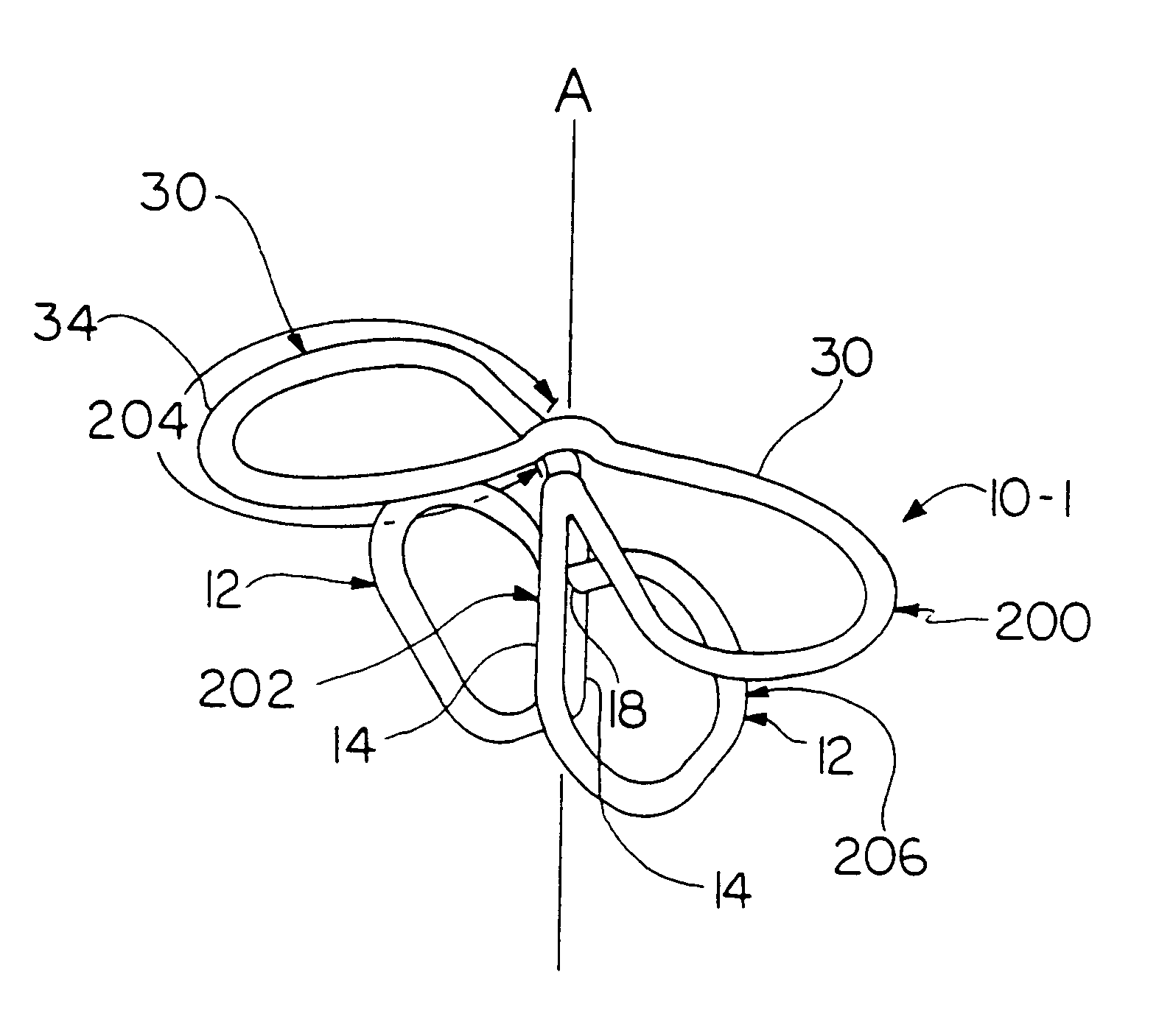
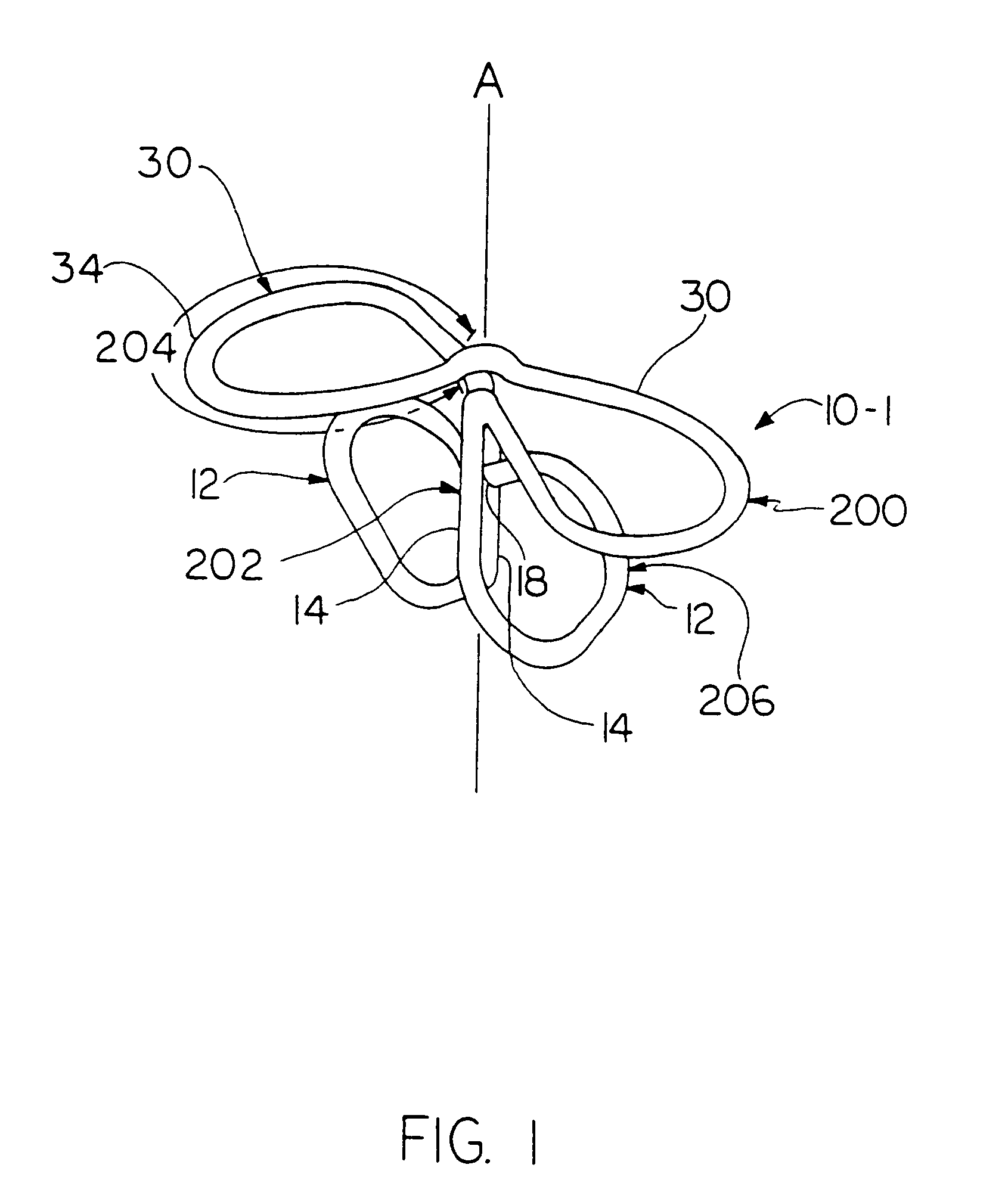
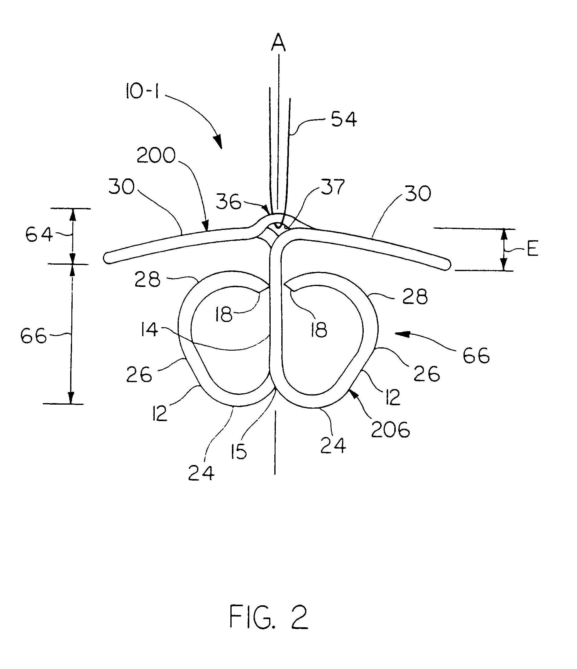
[0080]In the first embodiment in which the clip is designated generally 10-1 a central portion 14 leads into a pair of upper horizontally extending side arms 30 and into two lower elongated strand portions 12 that function to at least contact and preferably pierce the vessel wall and close the aperture.

[0081]Referring to FIGS. 1 through 5, 13 and 14, clip 10-1 for closing an aperture in a vessel includes a first portion 200 forming an arc. A second portion 202 extends transversely from first portion 200 relative to the arc where the arc is designated generally 204 in the drawings. A third portion 206 extends from second portion 202 remotely from first portion 200 and curves progressively, relative to second portion 202, initially towards first portion 200 and then towards second portion 202. A tip 18 of third portion 206 is adapted for piercing and retaining tissue encountered thereby.

[0082]In the drawings and particularly in FIG. 13 it is seen that second portion 202 embraces centr...

third embodiment

[0122]Referring to FIGS. 20 and 21, a tissue closure clip manifesting aspects of the invention is designated generally 10-3 and preferably includes a plurality of elongated strands, where the individual strands are designated generally 12-3 in FIGS. 20 and 21. Strands 12-3 may be single filaments or may be woven or braided or other arrangements of multiple sinuous members. Each elongated strand 12-3 preferably has a central portion and two (2) extremity portions extending in either direction from the central portion. Individual central portions of the elongated strands 12-3 are designated 14-3 while extremity portions of each elongated strand 12-3 are designated 16-3. Each extremity portion 16-3 terminates in a tip, where the tips of individual extremity portions are individually designated 18-3. Each tip 18-3 of an extremity portion 16-3 is shaped to retain tissue about the periphery of an aperture, which tissue is encountered by a tip 18-3 of tissue closure clip 10-3 as clip 10-3 ...

fourth embodiment

[0140]Referring to FIG. 28 illustrating a clip manifesting the invention where the clip is designated generally 10-4, clip 10-4 is preferably fabricated with an angle between vertical axis A and a line parallel with upwardly extending central segment 26-4 of third portion 204 equal to about thirty degrees (30°) where this angle is indicated by indicator AA in FIG. 28. Clip 10-4 is fabricated preferably with space between first portion 200-4 and the vertically upper extremity of third portion 206-4, designated by dimensional indicator BB in FIG. 28, being about 0.037 inches.

[0141]Clip 10-4 is further preferably fabricated with the radii of the arcs defining transition portion 24-4 between second portion 202-4 and forming the transition thereof into third portion 206-4 is formed preferably having a radius of about 0.048 inches as indicated by arrow CC in FIG. 28 and with transition 28-4 between the central part of third portion 206 and tip 18-4 being formed on a radius of about 0.063 ...


PUM


Abstract

An apparatus for closing an aperture comprising a horizontally extending member and elongated strand portions having extremity portions curving inwardly. The extremity portions have shape memory characteristics seeking to cause the extremity portions to curl to retain tissue engaged thereby when delivered from a delivery member. A central portion extends between the horizontally extending member and the elongated strand portions.

Description

CROSS-REFERENCE TO RELATED PATENT APPLICATION[0001]This application is a continuation of U.S. application Ser. No. 10 / 269,899, filed Oct. 11, 2002 now U.S. Pat. No. 6,749,622 which is a continuation of application Ser. No. 09 / 659,648, filed Sep. 12, 2000 now abandoned which claims priority from provisional application No. 60 / 153,736, filed Sep. 13, 1999.BACKGROUND OF THE INVENTION[0002]1. Field of the Invention[0003]This invention relates to methods and apparatus for closing apertures in human and animal tissue and to methods and apparatus for inserting apparatus into such tissue to perform such closure functions.[0004]2. Description of the Prior Art[0005]During certain types of vascular surgery, catheters are inserted through an incision in the skin and underlying tissue to access the femoral artery in the patient's leg. The catheter is then inserted through the access opening made in the wall of the femoral artery and guided through the artery to the desired site to perform surgic...

Claims


Application Information

Patent Timeline
Patent Type & Authority Patents(United States)
IPC IPC(8): A61B17/08A61B17/00A61B17/064
CPCA61B17/0057A61B17/064A61B2017/00637A61B2017/0641A61B2017/00668A61B2017/00867A61B2017/00659
Inventor MCGUCKIN, JR., JAMES F.MAURER, CHRISTOPHER W.PETERS, WALTER H.
Owner REX MEDICAL LP
Learn More