Earthquake resistant building foundation

Inactive Publication Date: 2008-05-01
HSU HAI TANG
View PDF11 Cites 32 Cited by
  • Summary
  • Abstract
  • Description
  • Claims
  • Application Information

AI Technical Summary

Benefits of technology

[0008]The primary objective of the present invention is to provide an earthquake resistant building foundation i

Problems solved by technology

However, the spherical support members may not be used to effectively reduce or cushion the sidewise or lateral forces.
However, similarl

Method used


Image

  • Earthquake resistant building foundation
  • Earthquake resistant building foundation
  • Earthquake resistant building foundation

Examples


Example

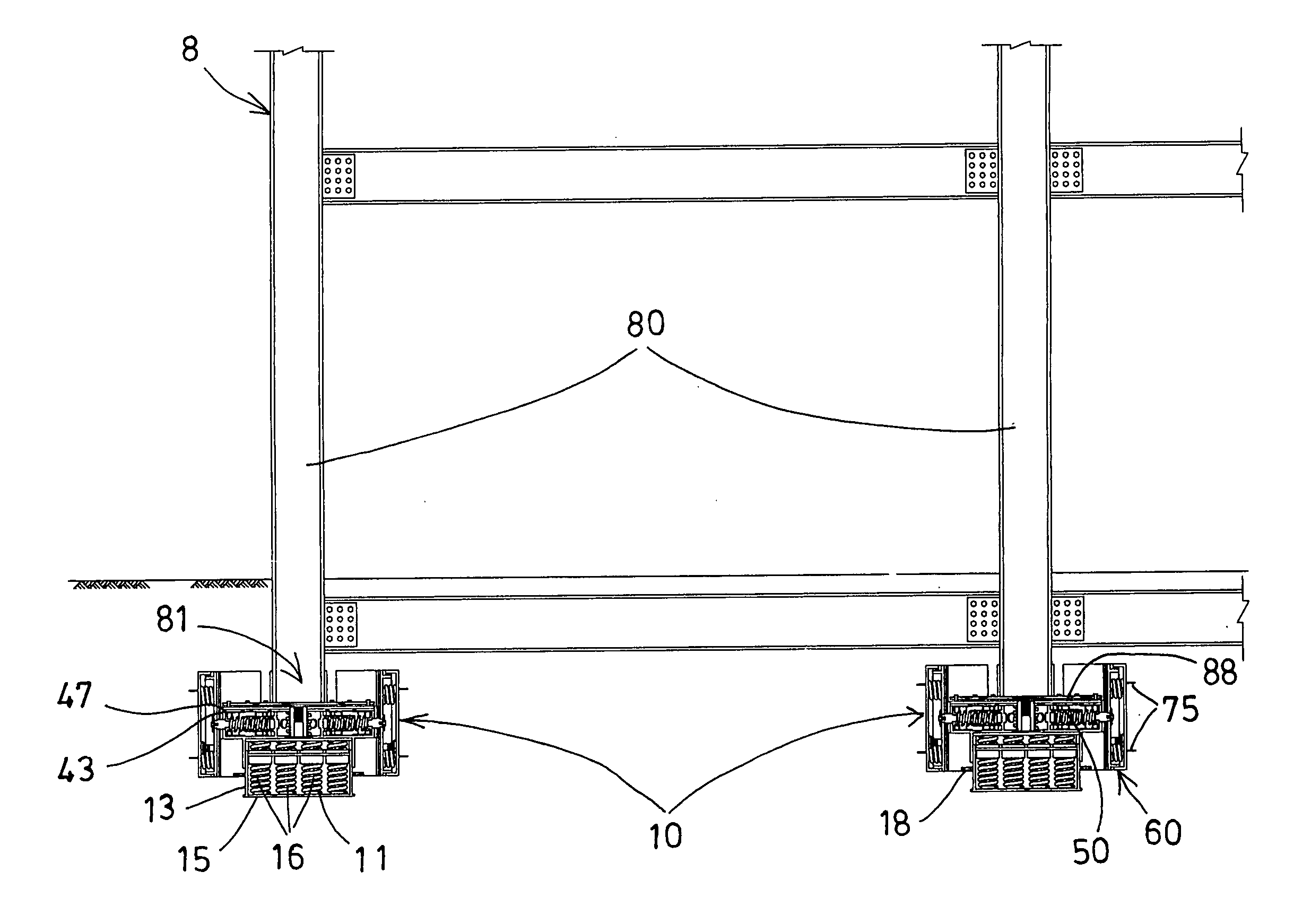
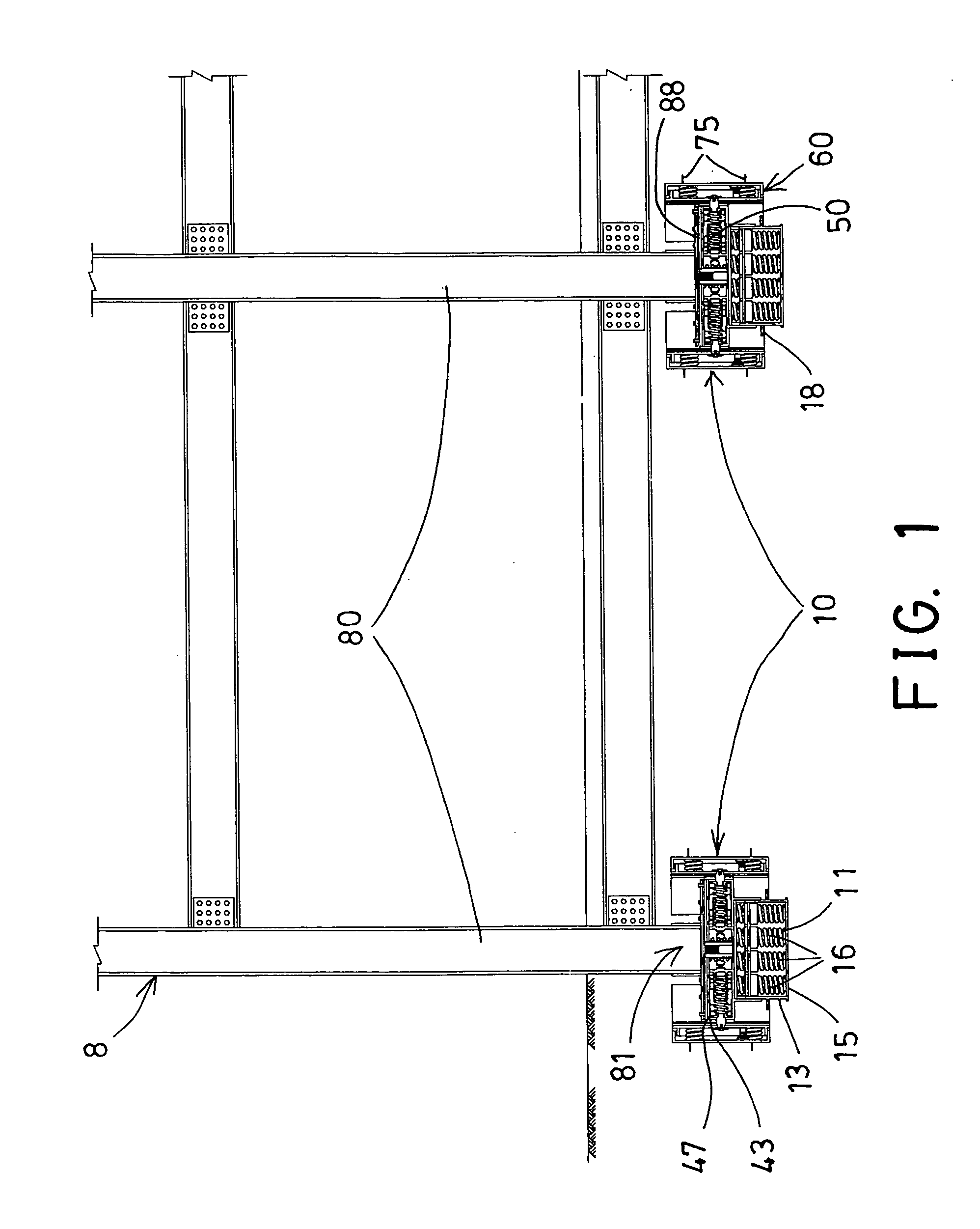
[0031]Referring to the drawings, and initially to FIG. an earthquake resistant building foundation 10 in accordance with the present invention is provided for being attached to or engaged with a lower portion of a construction 8, such as a house building 8, a bridge or the like, particularly, the earthquake resistant building foundation 10 is to be attached or secured to a bottom portion 81 of a beam or post 80 of the building 8 for resiliently cushioning and restraining the up and down or vertical forces or movements and sidewise or lateral forces or horizontal movements of the building resulting from earthquakes

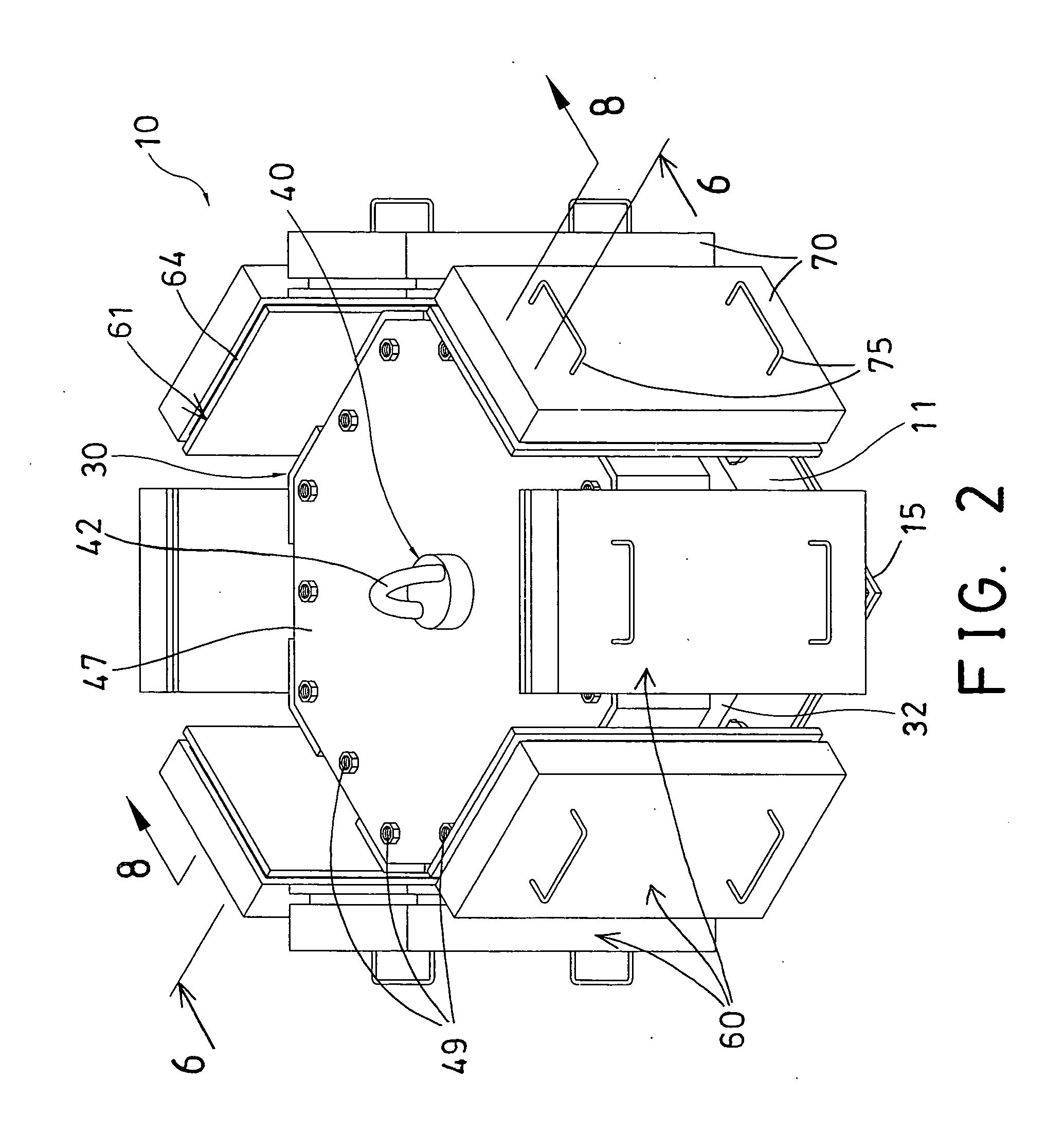
[0032]The earthquake resistant building foundation 10 comprises a lower or base housing 11 including a chamber 12 formed therein and defined by an outer peripheral wall 13 and a bottom wall 15, and including one or more rods 14 extended upwardly from the bottom wall 15 of the base housing 11 and located within the chamber 12 that is defined by the outer peripheral wall 13, ...


PUM


Abstract

An earthquake resistant building foundation includes a receptacle having a number of apertures each for slidably receiving a shaft, one or more spring members disposed below the receptacle for cushioning a vertical force, and a number of spring members engaged with the shafts for lateral cushioning purposes. A number of lateral cushioning devices are attached to the shafts and each has a casing secured to the shaft, a cover slidably engaged onto the casing, and one or more spring members engaged between the casing and the cover for cushioning between the casing and the cover and for forming a two-stage compressing or cushioning structure.

Description

BACKGROUND OF THE INVENTION[0001]1. Field of the Invention[0002]The present invention relates to an earthquake resistant building foundation, and more particularly to an earthquake resistant building foundation including an improved structure for resisting both up and down or vertical forces and sidewise or lateral forces.[0003]2. Description of the Prior Art[0004]Typical earthquake resistant buildings each comprise a number of foundations each including a number of spring members for resisting the up and down or vertical forces and the sidewise or lateral forces and for resiliently cushioning and restraining the horizontal movements of the building.[0005]For example, U.S. Pat. No. 4,517,778 to Nicolai discloses one of the typical earthquake proof building with an improved foundation comprising a number of spherical support members mounted thereon to support the structure. However, the spherical support members may not be used to effectively reduce or cushion the sidewise or lateral...

Claims


Application Information

Patent Timeline
IPC IPC(8): E04B1/98
CPCE04H9/021
Inventor HSU, HAI TANG
Owner HSU HAI TANG
Why Eureka
Try Eureka