

Piezoelectric Pump and Stirling Refrigerator/Freezer
a technology of stirring refrigerators and pumps, applied in the direction of positive displacement liquid engines, cooling devices, lighting and heating devices, etc., can solve the problem of inefficient operation of the stirring pump 106
- Summary
- Abstract
- Description
- Claims
- Application Information
AI Technical Summary
Benefits of technology
Problems solved by technology
Method used
Image

Examples
first embodiment
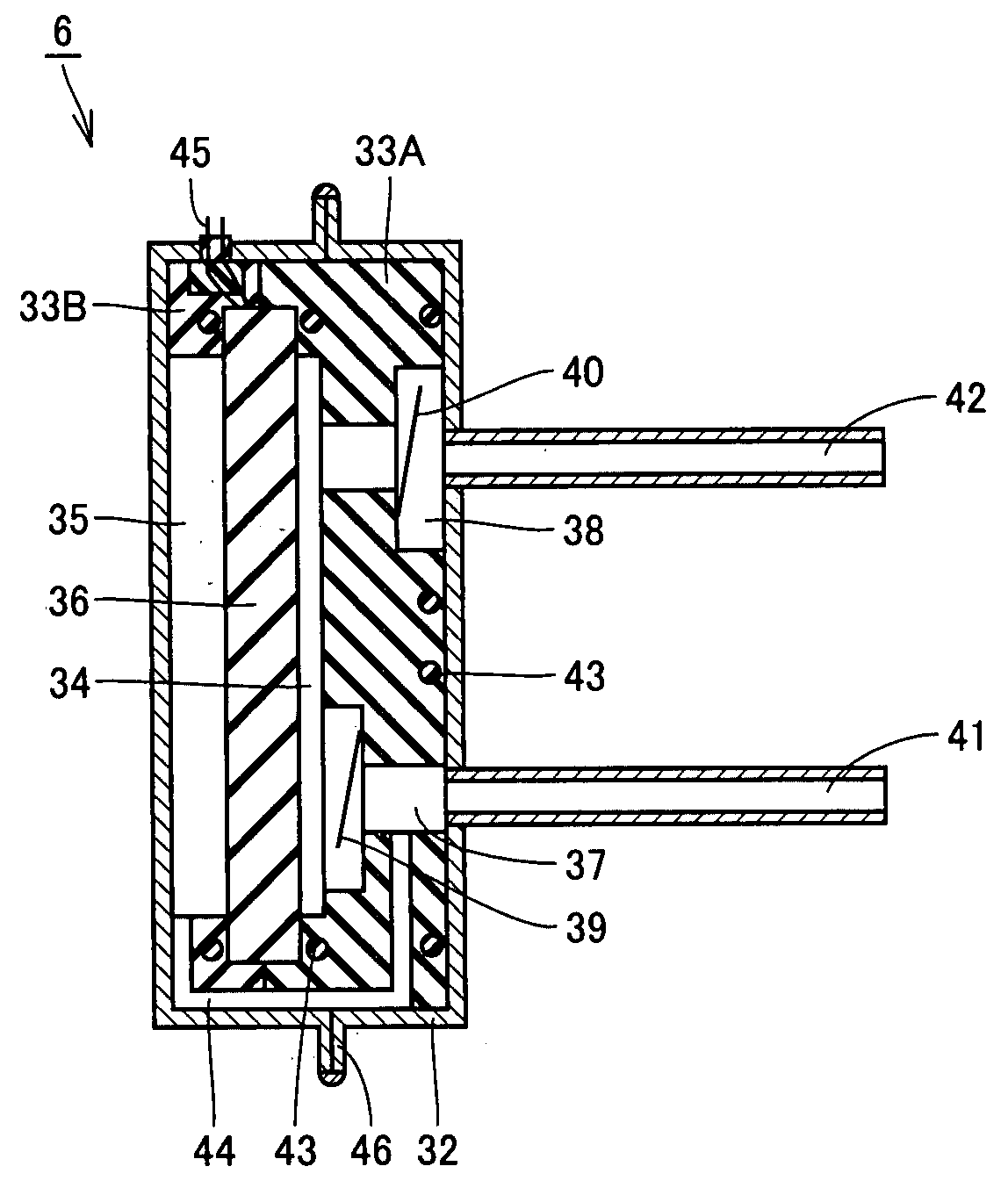
[0051]FIG. 2 is a cross section of a piezoelectric pump in a first embodiment.
[0052]The present embodiment provides a piezoelectric pump 6 including a casing 32 formed of a plurality of metallic members welded together, a piezoelectric element 36 dividing an internal space of casing 32 into a working space 34 (or a first internal space) and a back pressure space 35 (or a second internal space), and non-metallic, internal component 33A and 33B (or first and second internal components) provided between casing 32 and piezoelectric element 36 and holding piezoelectric element 36.
[0053]Internal components 33A and 33B are formed of workable and moldable resin. Internal component 33A defines a perimeter of working space 34 (or a pump chamber) and internal component 33B defines a perimeter of back pressure space 35. Internal components 33A and 33B are arranged opposite to each other to form a recess therebetween to receive and thus hold piezoelectric element 36 therein. In other words, inte...
second embodiment
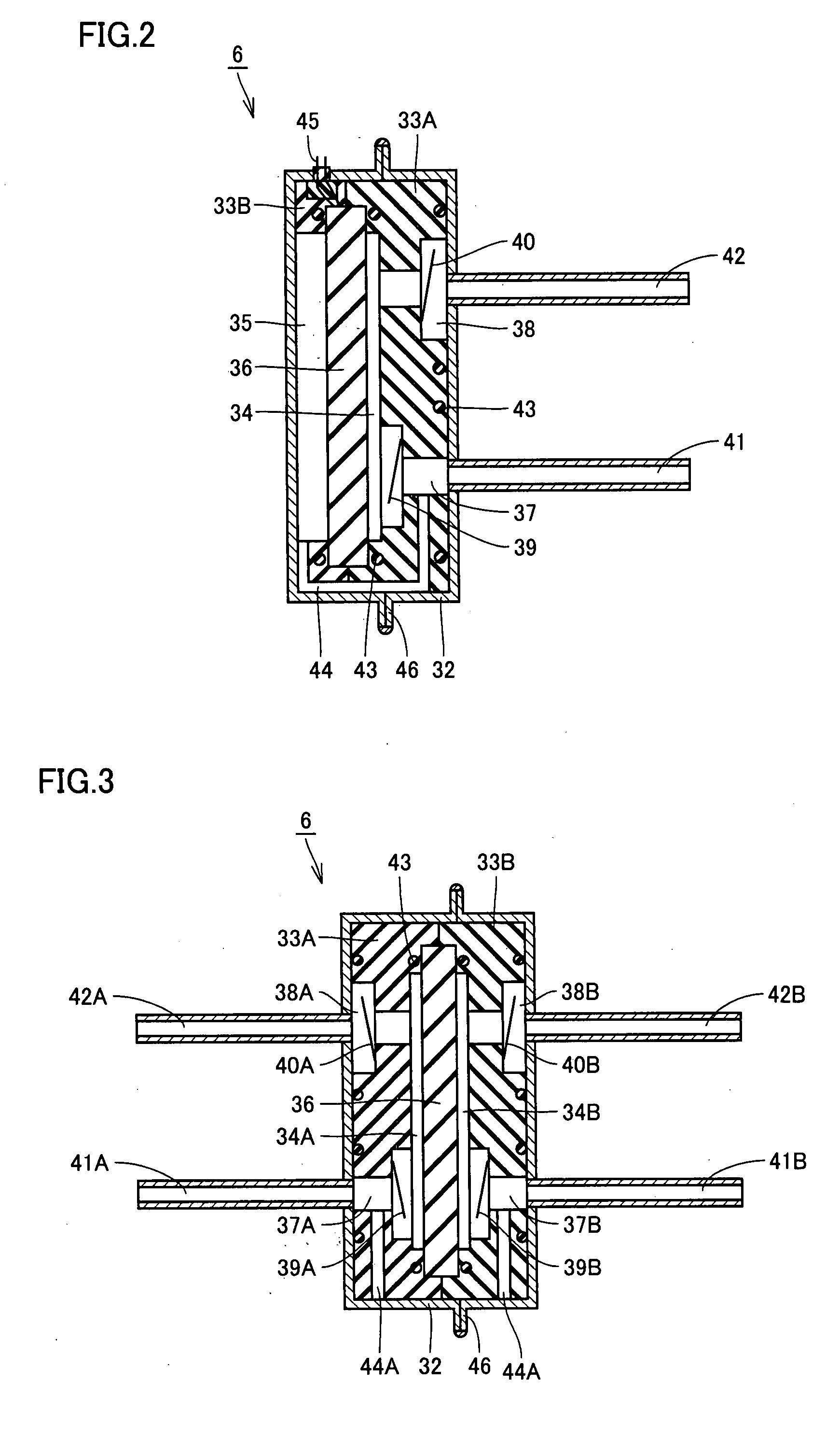
[0062]FIG. 3 is a cross section of a piezoelectric pump in a second embodiment.
[0063]Piezoelectric pump 6 in the present embodiment is an exemplary variation of piezoelectric pump 6 of the first embodiment and is characterized by employing opposite portions adjacent to piezoelectric element 36 as a pump chamber (or working spaces 34A and 34B).
[0064]As shown in FIG. 3, piezoelectric pump 6 is provided with an inlet 37A (or a first inlet) provided on internal component 33A (or a first internal component) to pass a working medium flowing from an inlet pipe 41A (or a first aspiration pipe) external to casing 32 toward working space 34A (or a first internal space), an inlet 37B (or a second inlet) provided on an internal component 33B (or a second internal component) to pass the working medium flowing from an inlet pipe 41B (or a second aspiration pipe) external to casing 32 toward working space 34B (or a second internal space), an outlet 38A (or a first outlet) provided on internal comp...
third embodiment
[0069]FIG. 4 is a cross section of a piezoelectric pump in a third embodiment.
[0070]Piezoelectric pump 6 in the present embodiment is an exemplary variation of piezoelectric pump 6 of the first embodiment and is characterized by employing opposite portions adjacent to piezoelectric element 36 as a pump chamber (or working spaces 34A and 34B).
[0071]As shown in FIG. 4, piezoelectric pump 6 is provided with inlet 37A (or the first inlet) provided on internal component 33A (or the first internal component) to pass a working medium flowing from inlet pipe 41 (or an aspiration pipe) external to casing 32 toward working space 34A (or the first internal space), inlet 37B (or the second inlet) provided on internal component 33B (or the second internal component) to pass the working medium flowing from inlet 37A toward working space 34B (or the second internal space), outlet 38A (or the first outlet) provided on internal component 33A to pass the working medium flowing from working space 34A ...
PUM
| Property | Measurement | Unit |
|---|---|---|
| Pressure | aaaaa | aaaaa |
| Moldable | aaaaa | aaaaa |
| Perimeter | aaaaa | aaaaa |
Abstract
Description
Claims
Application Information