Terminal fitting

a technology of fittings and fittings, applied in the direction of coupling contact members, coupling device connections, electrical devices, etc., can solve problems such as affecting contact stability, and achieve the effect of improving contact stability

Active Publication Date: 2008-05-01
SUMITOMO WIRING SYST LTD
View PDF8 Cites 10 Cited by
  • Summary
  • Abstract
  • Description
  • Claims
  • Application Information

AI Technical Summary

Benefits of technology

[0007]The invention relates to a terminal fitting, comprising a main portion into which a mating tab is insertable. A touching piece is provided at the main portion and has a projecting contact that can contact the tab. The contact has at least one flat surface that can be brought into flat contact (i.e. a contact other than a point contact, such as a line contact or a surface contact) with the tab when the tab is inserted properly into the main portion. Thus, the contact will not be streaked by the tab even if the tab moves loosely in the main portion due to vibration. As a result, contact stability can be improved.
[0012]The tab contacts the widthwise central part of the contact and may vibrate about a longitudinal axis at the contact due to vibration. However, the receiving portions support the opposite widthwise sides of the tab on a surface of the tab opposite the contact. Thus, vibration about the longitudinal axis is prevented and the contact and the tab are held in flat contact.
[0014]The flat surface of the contact preferably is formed to be gradually wider from a starting end with respect to the insertion direction of the tab to a rear end with respect to the insertion direction of the tab. Thus, insertion resistance at the initial stage of the insertion of the tab can be reduced to improve operability, whereas the flat surface can be held stably in contact with the tab after the completion of the insertion of the tab.
[0015]The main portion preferably has at least one projecting piece projecting substantially inwardly, and an excessive resilient deformation of the resilient touching piece can be prevented by contact with the projecting piece.

Problems solved by technology

However, the contact 6 might be streaked by the edges 9 to impair contact stability, for example, when the tab 2 moves loosely in the main portion 3 due to vibration.

Method used


Image

  • Terminal fitting
  • Terminal fitting
  • Terminal fitting

Examples


Embodiment Construction

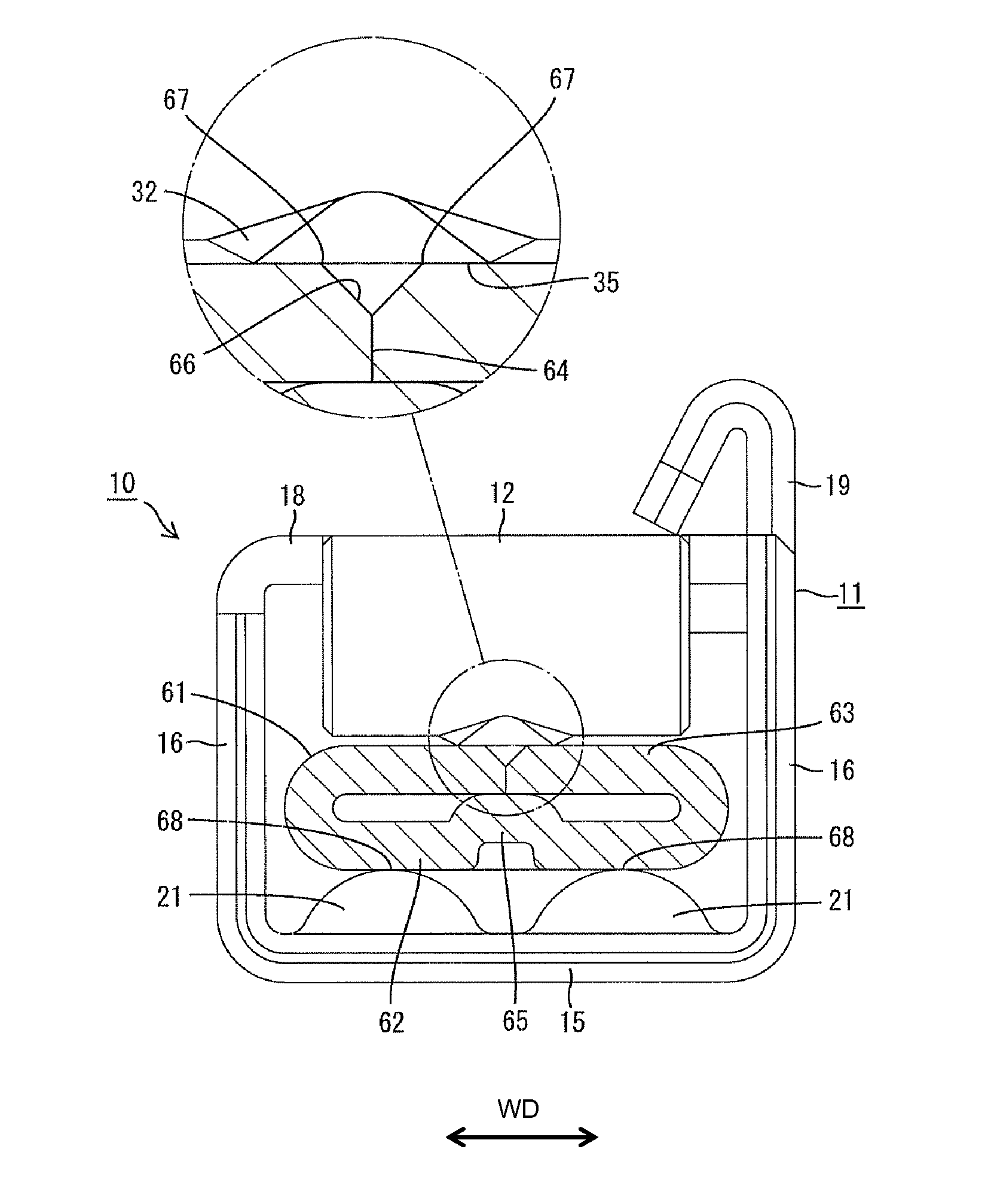
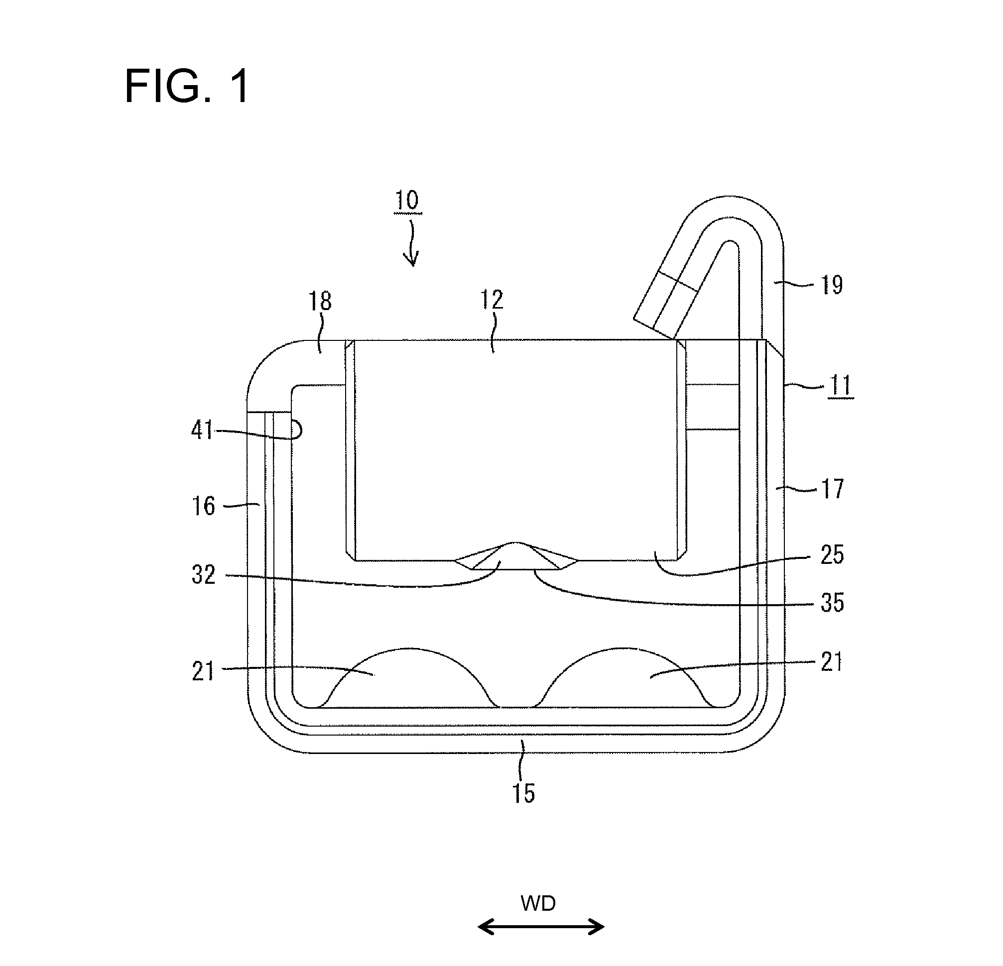
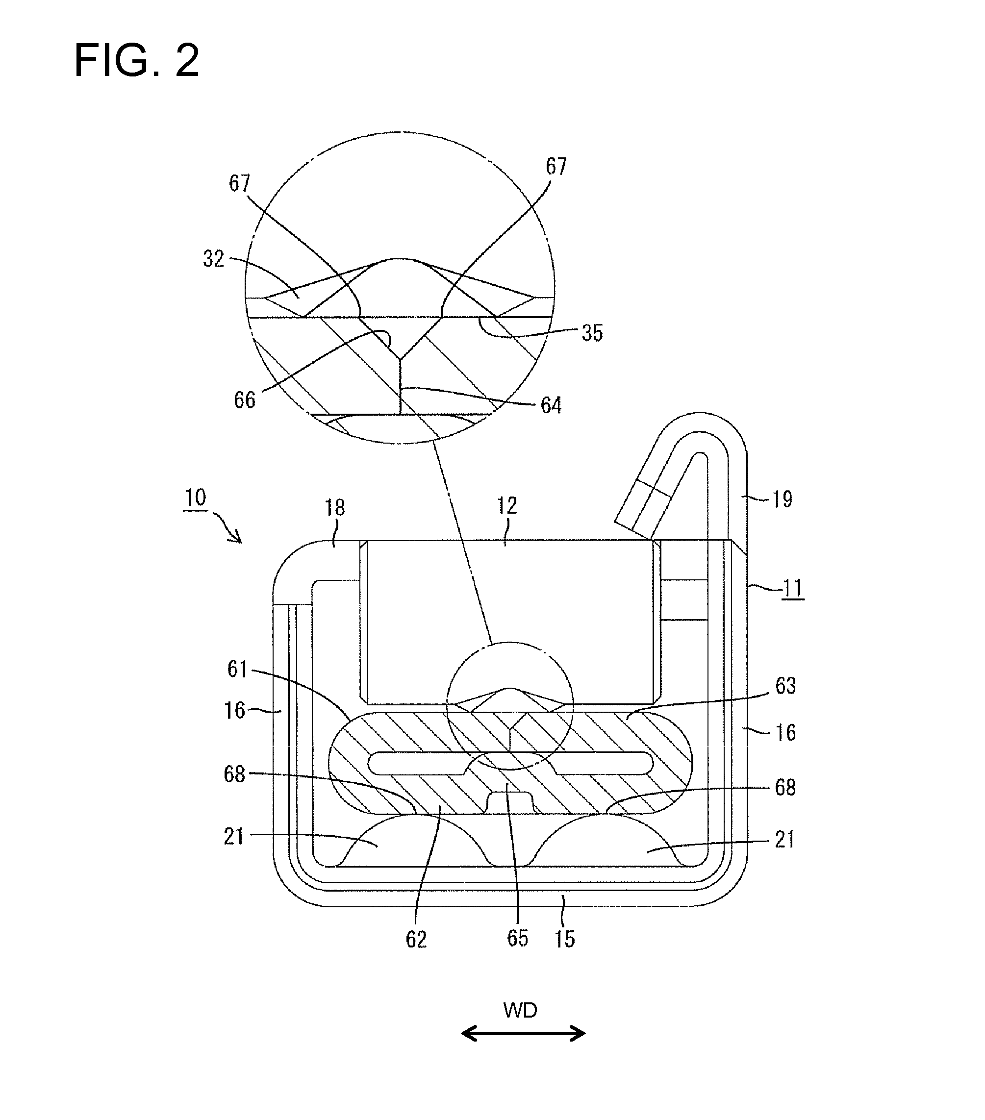
[0023]A female terminal fitting in accordance with the invention is identified by the numeral 10 in FIGS. 1 through 4. The female terminal fitting 10 can mate with a male terminal fitting 60 formed by bending an electrically conductive metal plate. Although not shown entirely, a tab 61 is formed at the leading end of the male terminal fitting 60 and extends in forward and backward directions FBD. The tab 61 is formed by folding the opposite left and right edge portions of the conductive metal plate in a thickness direction and causing the side edges of the folded parts to be in face to face contact with each other. Thus, the tab 61 includes a base wall 62 and left and right covering walls 63 folded on the base wall 62. Facing ends 64 of the covering walls 63 are arranged substantially in the widthwise center of the tab 61. A supporting mount 65 is embossed to project from the base wall 62 towards the facing ends 64. A clearance corresponding to a projecting amount of the supporting ...


PUM


Abstract

A female terminal fitting (10) is provided with a box-shaped main portion (11) into which a mating tab (61) is insertable, and a resilient touching piece (12) having a projection as a contact projection (32) that can contact the tab (61) is provided in the main portion (11). The tab is formed by folding the opposite widthwise sides of a metal plate in a thickness direction and causing the end edges of the folded parts to face each other. A flat surface (35) of the contact projection (32) comes into flat contact with the tab (61) while crossing over the facing ends (64) when the tab (61) is inserted properly into the main portion (11). Accordingly, edges (67) of the facing ends (64) do not sharply act on the contact projection (32).

Description

BACKGROUND OF THE INVENTION[0001]1. Field of the Invention[0002]The invention relates to a terminal fitting and to a connecting method therefor.[0003]2. Description of the Related Art[0004]Japanese Unexamined Patent Publication No. 2005-44598 and FIG. 5 herein disclose a female terminal fitting 4 with a box-shaped main portion 3 configured for receiving a mating tab 2. A resilient touching piece 5 is formed in the main portion 3. A contact projects from the upper surface of the resilient touching piece 5 and has a curved projecting piece. An elongated receiving portion 7 projects at a position on the inner surface of the main portion 3 facing the contact 6. The tab 2 has a double-plate structure by folding opposite widthwise ends of a metal plate in the thickness direction and causing the end edges of the folded parts to face each other. The tab 2 is inserted into the main portion 3 from the front so that the facing ends 8 face towards the contact 6. The resilient touching piece 5 i...

Claims


Application Information

Patent Timeline
Patent Type & Authority Applications(United States)
IPC IPC(8): H01R13/22
CPCH01R13/193H01R13/113H01R13/11
Inventor MUNEYASU, KAZUHIDE
Owner SUMITOMO WIRING SYST LTD
Why Eureka
Try Eureka