Port security barrier

a security barrier and port technology, applied in the field of security barriers, can solve the problems of maintaining low levels for further operational costs

Active Publication Date: 2008-05-08
UNITED STATES OF AMERICA
View PDF13 Cites 29 Cited by
  • Summary
  • Abstract
  • Description
  • Claims
  • Application Information

AI Technical Summary

Benefits of technology

[0011]One end of the barrier float assembly is designed to accommodate a latching mechanism that is used to couple the barrier float assembly to a mooring buoy. The latching mechanism allows the barrier float assembly to be swung open and then closed acting as a gate for vessel traffic which passes through the assembly into and out of a port facility.

Problems solved by technology

Further operational cost need to be kept at low levels.

Method used


Image

  • Port security barrier
  • Port security barrier
  • Port security barrier

Examples


Embodiment Construction

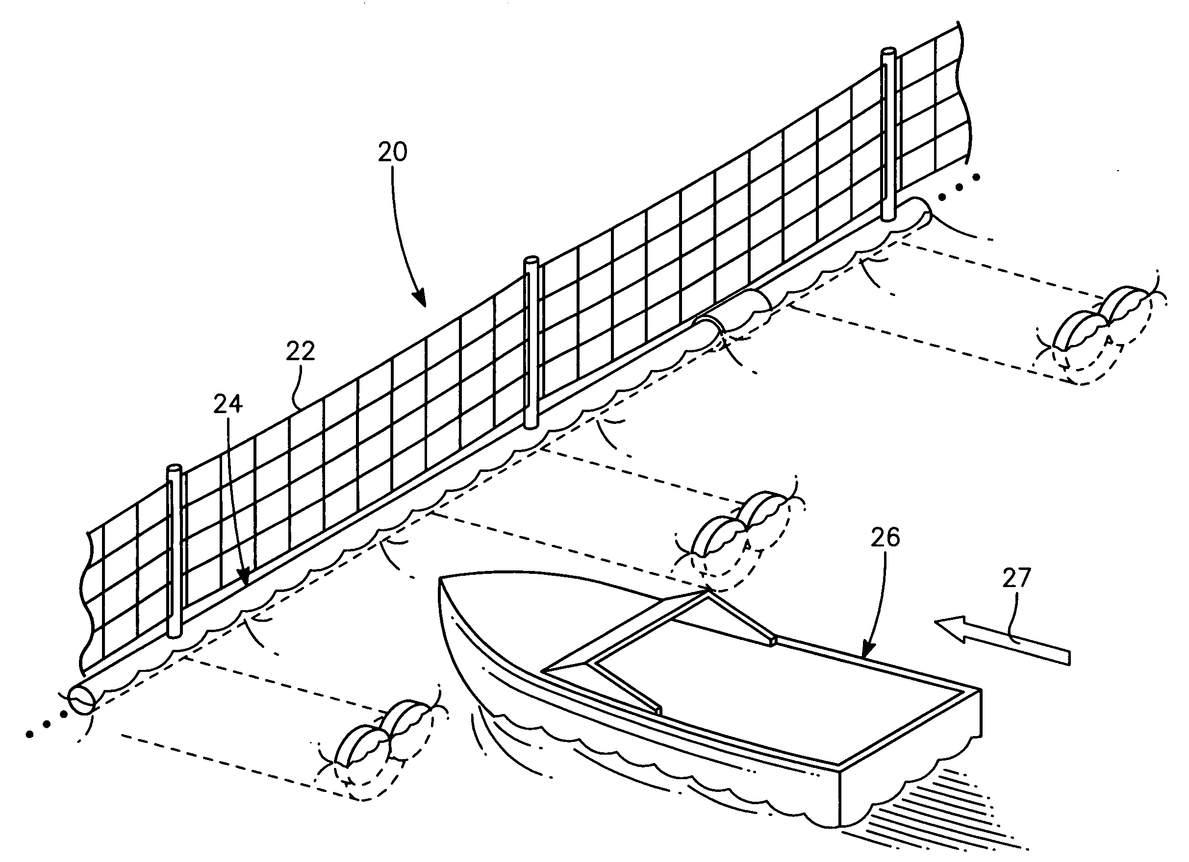
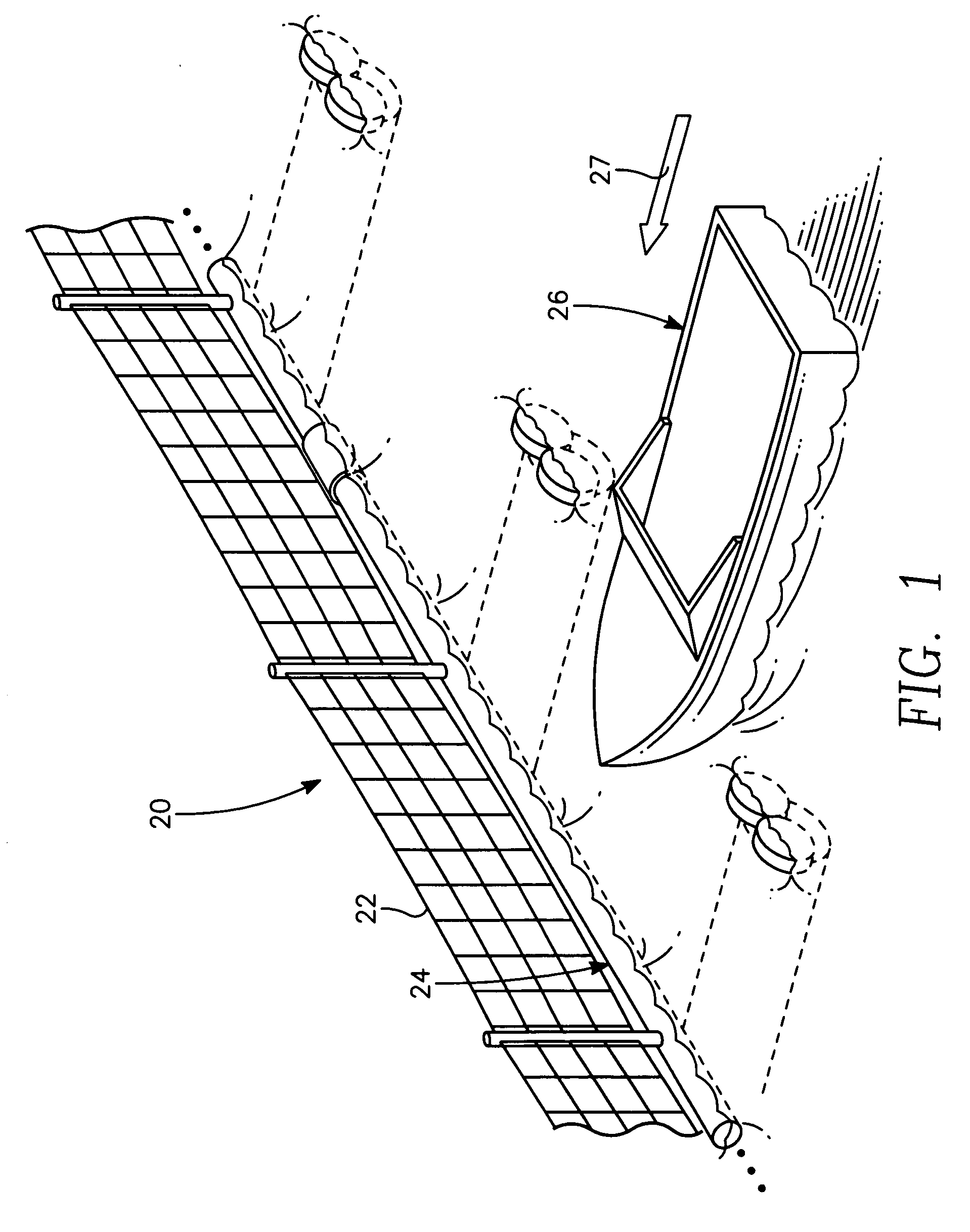
[0020]Referring to FIGS. 1-4, the port security barrier 20 is a moored nylon barrier net 22 and pontoon structure 24 that provides waterfront security to stop, delay or discourage attack by boats 26 of 65 feet less on high value waterfront assets. The nylon net 22, it attachments and connection to its moorings provide the main boat stopping capability for boats traveling in the direction indicated by arrow 27. The supporting pontoon structure 24 holds the nylon net 22 in position and also serves to dissipate a portion of the kinetic energy from the attacking boat 26.

[0021]The port security barrier 20 is designed to protect ocean going vessels and watercraft and stop approximately 99.9% of United States commercial boats with a minimum working stopping capacity of approximately 1.8 million foot-pounds of kinetic energy. The barrier 20 also has a factor of safety to increase net replacement time, thus, the net boat stopping capacity is approximately 3.6 million foot-pounds.
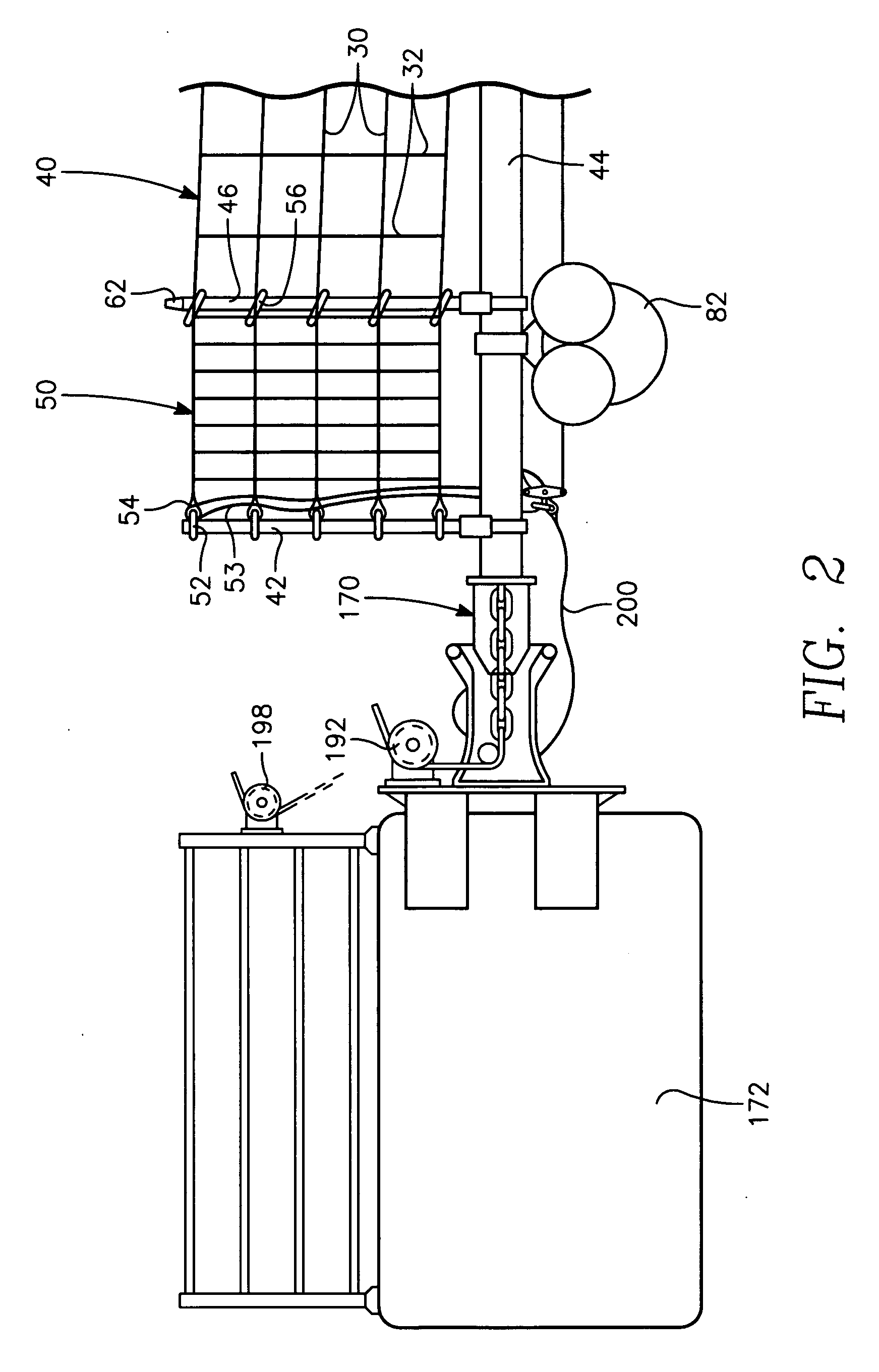
[0022]The ny...


PUM


Abstract

The port security barrier includes multiple barrier float assemblies connected to one another to form a barrier to stop, delay and discourage attacks by high speed boats of sixty five feet or less in length on high valued waterfront assets such as ports and docking facilities. The port security barrier includes multiple barrier floats coupled to one another by flange connectors. Each barrier float assembly also has a capture nylon net which is used to capture the high speeds and prevent an intrusion into restricted waters.

Description

BACKGROUND OF THE INVENTION[0001]1. Field of the Invention[0002]The present invention relates generally to a security barrier for use at a port or the entrance to an inland waterway which receives ships laden with cargo or military watercraft. More specifically, the present invention relates to a port security barrier which is economical, easy to transport and assemble and provides sufficient strength to stop, delay and discourage attacks by boats of 65 feet or less in length on high valued waterfront assets.[0003]2. Description of the Prior Art[0004]There is currently a need within the Department of the Navy to provide protection for military watercraft which are moored at ports or inland waterways. In particular, there is a need to provide protection for military watercraft against explosive laden boats while the watercraft are moored at a port or an inland waterway.[0005]There is also need to keep initial cost as low as possible and also meet military security requirements by (1)...

Claims


Application Information

Patent Timeline
Patent Type & Authority Applications(United States)
IPC IPC(8): B63G9/04
CPCF41H11/05B63G9/04
Inventor NIXON, LAURENCESEELIG, WILLIAMSLAUGHTER, STEPHEN
Owner UNITED STATES OF AMERICA
Why Eureka
Try Eureka