
First stage scuba diving regulator having an intermediate pressure spring protected from ice-induced blockage

Active Publication Date: 2008-05-08
HUISH OUTDOORS
View PDF8 Cites 4 Cited by
  • Summary
  • Abstract
  • Description
  • Claims
  • Application Information

AI Technical Summary

Benefits of technology

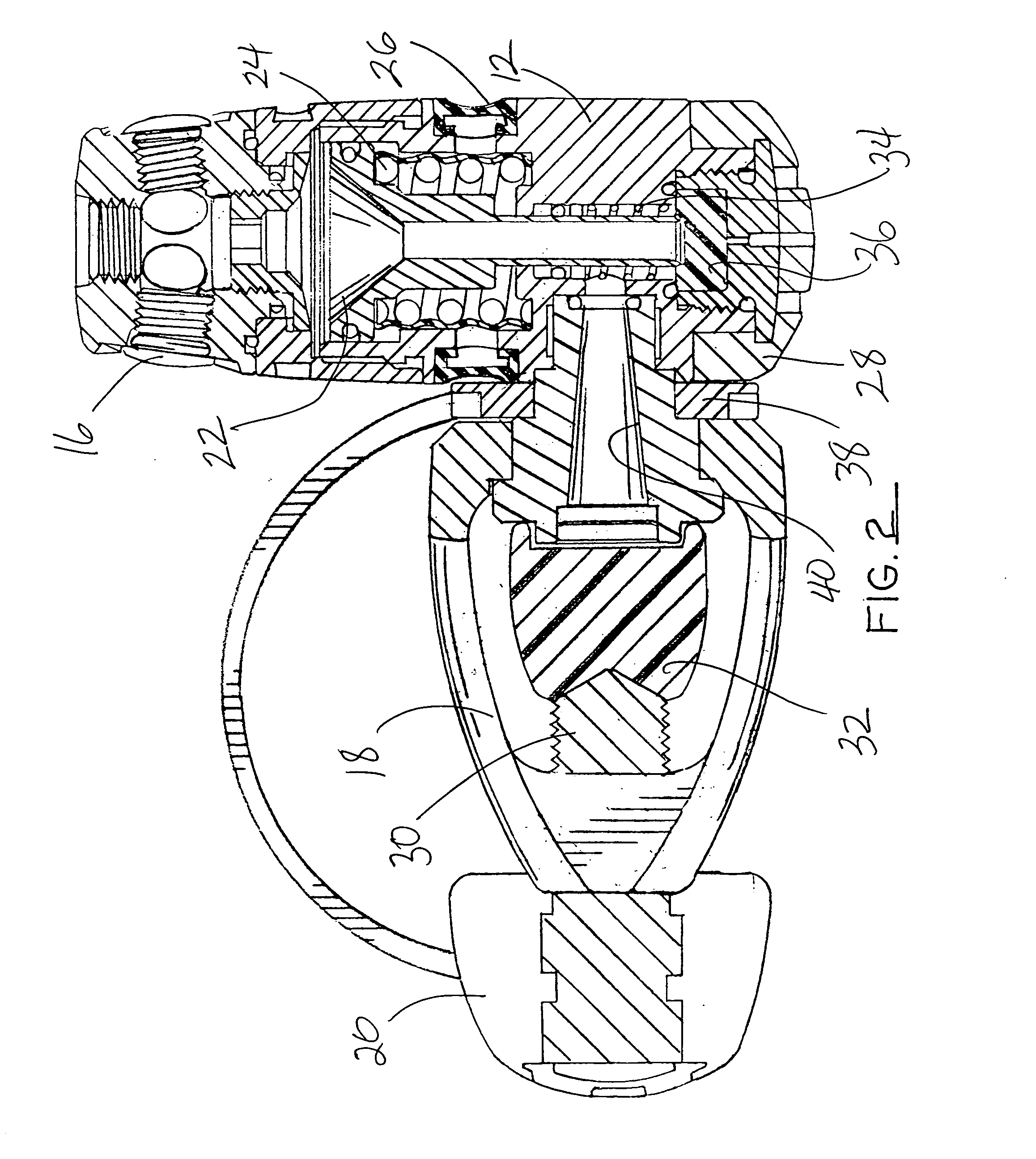
[0018]In the present invention soft silicone rubber is bonded to the first stage spring to prevent water from freezing between the coils of the spring thereby assuring unrestricted movement of the spring coils even during freezing conditions.
[0021]In addition to bonding the spring with a pliable silicone material that encapsulates or cocoons the entire spring to prevent freezing, a flexible diaphragm or membrane may be employed and secured to the first stage body to function as a barrier to resist water and debris from entering the ambient pressure cavity. With this optional flexible diaphragm, no exchange of water or contamination is permitted inside the first stage. This further reduces the chance of freezing.
[0023]In order to remove any added resistance or compressive stresses to the spring that could occur as a result of molding any materials between the coils of the spring, a molding method is needed to eliminate interference between the spring coils.
[0026]As the spring is assembled into the first stage and tightened to the correct assembled height, the silicone material will be significantly less stretched. Additionally, when the first stage is pressurized with air and the piston travels forward to make contact with the high-pressure seat, it will now have no added silicone induced stresses and the spring will be at the proper working height and the silicone material is static, thus the first stage intermediate pressure is stable.

Problems solved by technology

This further reduces the chance of freezing.

Method used


Image

  • First stage scuba diving regulator having an intermediate pressure spring protected from ice-induced blockage
  • First stage scuba diving regulator having an intermediate pressure spring protected from ice-induced blockage
  • First stage scuba diving regulator having an intermediate pressure spring protected from ice-induced blockage

Examples


Embodiment Construction

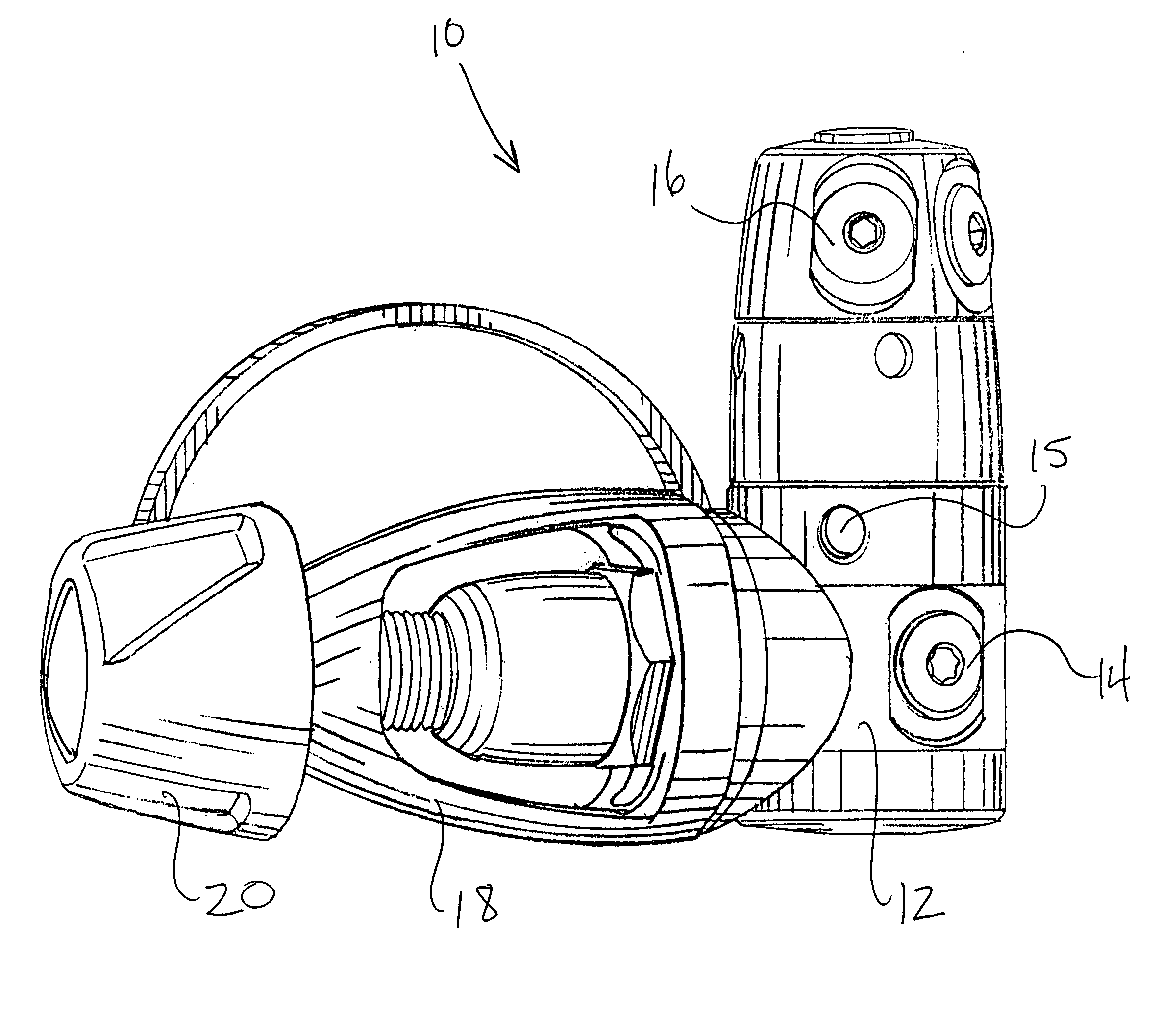
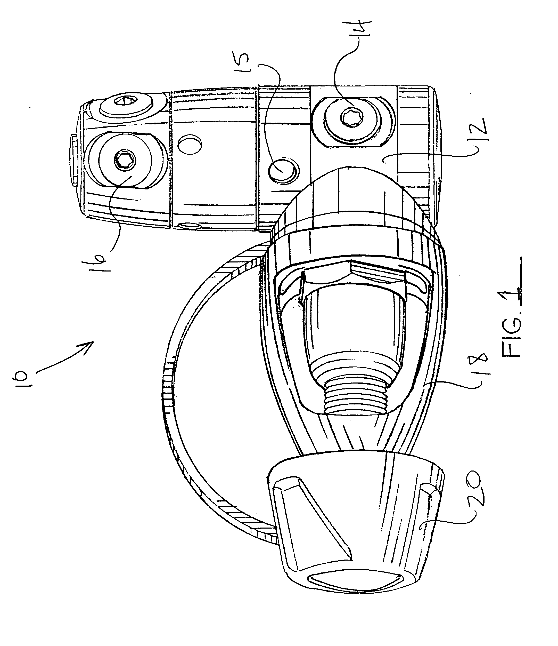
[0034]Referring to the accompanying drawings, it will be seen that a first stage pressure regulator 10 according to the present invention is a type of balanced regulator which uses a piston 22 to receive compressed air at a high pressure up to 300 Bar (4350 psi) and provide an intermediate pressure at 135 psi over ambient. The piston is of a flow through or hollow stem design having a large sensing end and a smaller valve seating end. The piston is designed for limited travel toward and away from the valve seat 36. Travel toward the valve seat is resisted by the intermediate pressure spring 24. The piston moves away from the high pressure seat a sufficient distance to permit a free flow of air through the stem and toward the sensor end. As the air flow continues, pressure builds at the pressure sensing end and tends to force the piston toward the high pressure seat against the intermediate spring compression force until airflow is halted by the seating of the smaller end of the pist...


PUM


Abstract

In a scuba diving first stage pressure regulator soft silicone rubber is bonded to the first stage spring to prevent water from freezing between the coils of the spring thereby assuring unrestricted movement of the spring coils even during freezing conditions. By placing a soft molded material bonded directly to the spring surface through the method of chemical and / or mechanical bonding, a soft pliable silicone rubber encapsulates or cocoons the entire area between spring coils and works as a barrier to prevent water from filling the regions between the spring coils and freezing in cold diving conditions. The thickness and volume of the pliable material silicone is not critical as long as the area between the coils is occupied with enough material to prevent ice from forming and otherwise preventing the spring from deflecting. Further, a radial clearance hole is needed to allow the piston to fit inside the silicone bonded spring hollowed center. Any extra area in the spring hole may be filled with a freeze resistant material such as Teflon or silicone grease.

Description

BACKGROUND OF THE INVENTION[0001]1. Field of the Invention[0002]The present invention relates generally to scuba diving first stage pressure regulators. The invention relates more specifically to a silicone or rubber-like material bonded onto a first stage regulator intermediate pressure spring for the purpose of providing freeze protection and to a method of molding silicone or rubber-line material to a compressed first stage spring to eliminate any induced stress added by the material. The use of a flexible membrane or diaphragm used in eliminating water and contamination from entering the ambient pressure cavity where the spring is housed is also described.[0003]2. Background Art[0004]Scuba diving first stage regulators need freeze protection if used in waters lower than 50 degrees Fahrenheit (10 degrees Celsius).[0005]Flow through piston regulators can freeze “open” when used in cold water conditions if not fitted with proper antifreeze or environmental provisions. When this “op...

Claims


Application Information

Patent Timeline
IPC IPC(8): B63C11/18
CPCG05D16/103B63C11/2209Y10T137/7808Y10T137/7036Y10T137/7801Y10T137/2036
Inventor GARRAFFA, DEAN R.
Owner HUISH OUTDOORS
Learn More