Membrane pump with stretchable pump membrane

a membrane pump and membrane technology, applied in the field of membrane pumps, can solve the problems of increased pressure inside the pumping chamber, less suitable gas pumping, and opening of the outlet valv

Inactive Publication Date: 2005-09-27
NOVO NORDISK AS
View PDF15 Cites 388 Cited by
  • Summary
  • Abstract
  • Description
  • Claims
  • Application Information

AI Technical Summary

Benefits of technology

[0047]Using a membrane pump as a suction pump in a drug delivery device, a hydraulically much stiffer system can be achieved as the reservoir is “behind” the pump. Correspondingly, by also paying attention to the compliance of the o

Problems solved by technology

When a voltage is applied, an increase of the pressure inside the pumping chamber occurs, which causes the opening of the outlet valve.
One disadvantage with this type of micropump is that the silicon membrane's warping is slight in comparison with the size of the pump chamber, this making the pump less suitable for pumping of gas.
Further, the manufacturing costs for silicon-based micropumps are very high, making this technology at present unsuitable for a disposable pump.
However, the above-described micropumps suffer in this respect, from certain imperfections.
Thus, the same voltage applied to micropumps apparently identical may cause differing deformations of the pumping chamber of these micropumps, which, subsequently, will produce differing flow rates.
Furthermore, for a given micropump, the flow rat

Method used


Image

  • Membrane pump with stretchable pump membrane
  • Membrane pump with stretchable pump membrane
  • Membrane pump with stretchable pump membrane

Examples


second embodiment

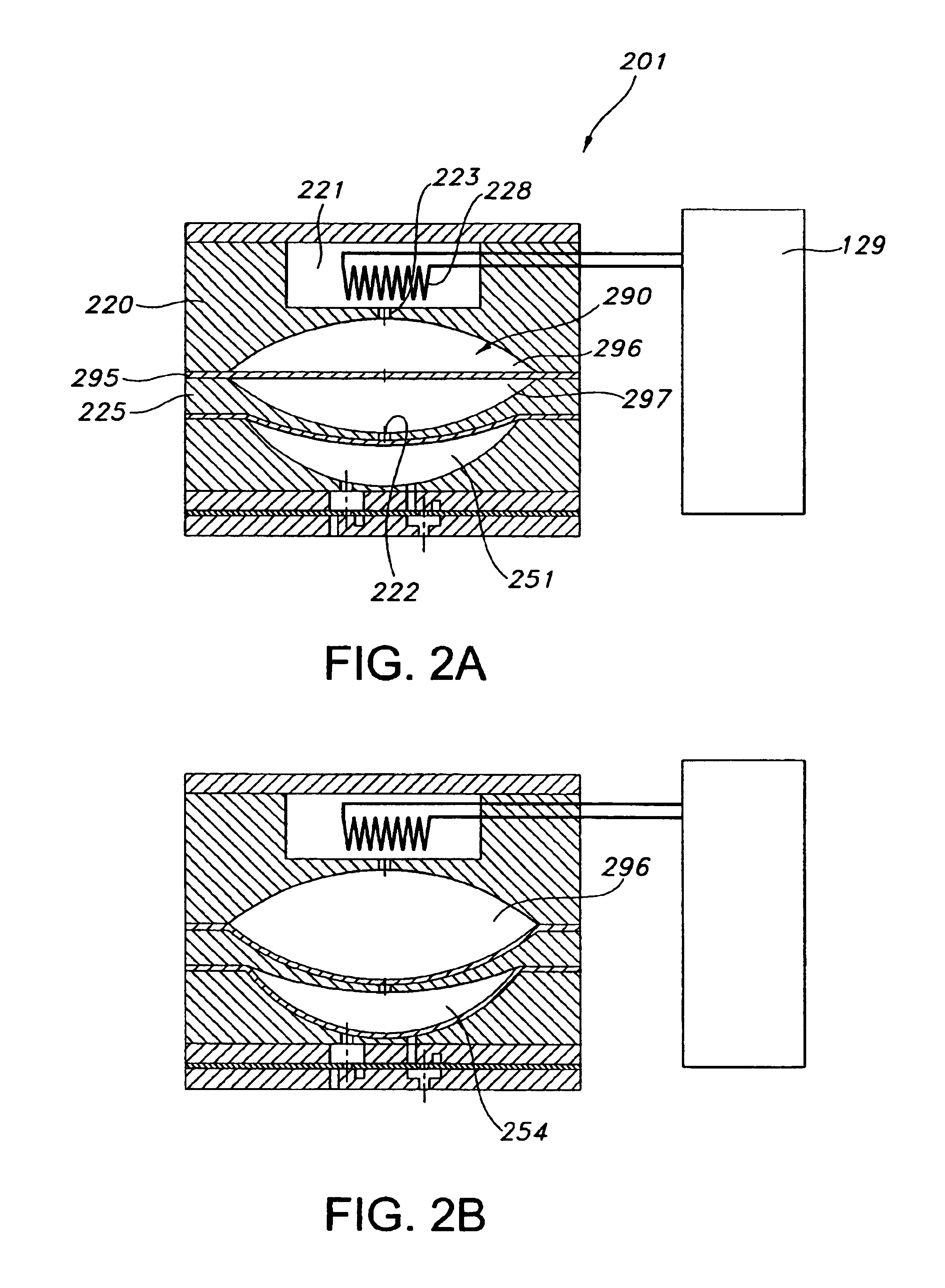
[0094]Next, with reference to FIGS. 2A and 2B, a pump 201 comprising a transmission cavity with a transmission membrane will be described.

[0095]In respect of the pump “as such” (i.e. the pump chamber, valves, fluid chamber and heating structure) the second embodiment corresponds in general to the first embodiment, however, the pump 201 comprises first and second intermediate housing portions 220, 225 instead of the single intermediate housing portion 120. A transmission cavity 290 is formed between concave wall portions 291, 292 of the first respective the second intermediate housing portions which in combination define the boundaries for the transmission cavity. Arranged between the first and second intermediate housing portions an elastic membrane forms a transmission membrane 295 dividing the transmission cavity in an upper inlet chamber 296 and a lower outlet chamber 297 sealed from each other by the transmission membrane. In the shown embodiment the inlet chamber has an initial...

third embodiment

[0097]Next, with reference to FIGS. 3A and 3B, a pump 301 will be described.

[0098]In respect of the pump “as such” (i.e. the pump chamber, valves, and fluid chamber) the third embodiment corresponds in general to the first embodiment, however, there are two differences. Firstly, the upper wall portion 353 defining the upper boundary for the pump cavity is substantially planar, the pump membrane thereby resting thereon in an un-stretched state. Secondly, the pump fluid is displaced from the pump chamber 321 by means of an actuator membrane 327 arranged between the upper and intermediate housing portions 330, 320. Corresponding to the fluid chamber the actuator membrane is provided with a disc-formed piezoelectric element 328 which can be shifted between a first generally planar configuration and a second downwardly curved configuration by control means 329.

[0099]The third embodiment may be provided either as an integral unit comprising both cavities, or as a system comprising a pump ...

fifth embodiment

[0105]With reference to FIG. 6, a pump 601 will be described, the pump essentially corresponding to the forth embodiment, however, the pump membrane comprises a passive electrode 602 whereas each of the opposed pump cavity walls are provided with a pair of “active” electrodes 603, 604 connected to the control means. In this way it will be possible to detect movement of the pump membrane relative to both of the wall portions providing improved control. The active electrodes 702, arranged either on the pump membrane 740 or a housing wall, may be configured as shown in FIG. 7, whereas the passive electrodes may be formed as a single disc-formed area, however, numerous configurations for the electrodes would be possible depending on the type of electrodes and the configuration of the control and detecting means.


PUM


Abstract

The invention relates to membrane pumps for delivering liquids. More specifically, a pump is provided having a pump housing with a pump cavity formed between first and second wall portions thereof, and an pump membrane pump membrane having first and second membrane surfaces arranged within the pump cavity, whereby a pump chamber is provided between the first wall portion and the first membrane surface, and an actuation chamber is provided between the second wall and the second membrane surface. Inlet means comprising an inlet valve in fluid communication with the pump chamber, and outlet means comprising an outlet valve in fluid communication with the pump chamber are provided. The pump membrane has a maximum volume position, and a drained volume position in which the first membrane surface in a stretched state abuts the first wall. To drive the membrane, actuating means for periodically shifting the pump membrane between the maximum volume position and the drained volume position is provided, thereby, in a situation of use, providing a flow of fluid.

Description

CROSS-REFERENCE TO RELATED APPLICATIONS[0001]This application claims priority under 35 U.S.C. 119 of European application no. EP 02388066.9 filed Sep. 27, 2002, and U.S. provisional application No. 60 / 416,856 filed Oct. 8, 2002, the contents of which are fully incorporated herein by reference.FIELD OF THE INVENTION[0002]The present invention relates to membrane pumps for delivering liquids. More specifically, the invention relates to micro membrane pumps suitable for pumping liquids as well as gasses, such pumps being suitable in particular for the in situ administration of medicinal drugs, the miniaturization of the pump allowing a user to carry the same on the body, or even to have the pump implanted directly in the body. Furthermore, such pumps can be used in areas such as biochemistry, microbiology, chemical analysis, and micro-reaction setups.BACKGROUND OF THE INVENTION[0003]Micropumps, i.e. pumps adapted for providing flow rates for liquids in the range of 1 μl / hour to 1 ml / mi...

Claims


Application Information

Patent Timeline
IPC IPC(8): A61M5/145A61M5/155F04B43/06F04B43/02F04B43/04F04B19/24F04B19/00A61M5/142F04B17/00
CPCA61M5/14224A61M5/14248A61M5/14593A61M5/155F04B19/24F04B43/02F04B43/043F04B43/06F04B53/1067F16K99/0001F16K99/0015F16K99/0057A61M2005/14252A61M2005/14268A61M2205/0244A61M2205/0294A61M2205/36A61M2205/3653F04B2201/0201F16K99/0034F16K2099/0086F16K2099/0094
Inventor HANSEN, STEFFEN
Owner NOVO NORDISK AS
Why Eureka
Try Eureka