Mold closing device for an injection molding machine

a technology of injection molding machine and closing device, which is applied in the direction of dough shaping, application, manufacturing tools, etc., can solve the problems of inability to maintain the parallelism between the plate and the machine frame stationary outer mold mounting plate, disadvantages, and inability to accurately close the unit, etc., to achieve short construction, increase compressibility, and reduce the effect of stiff system

Inactive Publication Date: 2006-06-01
KRAUSSMAFFEI TECH GMBH
View PDF14 Cites 4 Cited by
  • Summary
  • Abstract
  • Description
  • Claims
  • Application Information

AI Technical Summary

Benefits of technology

[0012] According to another advantageous feature of the invention, a supporting frame may be fixedly connected to a machine frame for rotatably supporting the center mold carrier element, wherein the outer mold mounting plates are constructed for slidable support on the machine frame and movement to and away in relation to the center mold carrier element. When the supporting frame for the center mold carrier element is attached to the machine frame according to the invention, the center mold carrier element can be supported in a more massive and hence more robust rotary device, while on the other hand each of the two outer mold mounting plates moves back and forth directly and with a short displacement, i.e., without an intermediate moveable mold mounting plate, relative to the stationary supporting frame of the center mold carrier element.
[0016] According to another advantageous feature of the present invention, the support plate and the associated outer mold mounting plate may form a sandwich plate with an interposed hydraulic pressure piston. This plate arrangement has a very short construction and represents a particularly stiff system because the quantity of hydraulic fluid needs to be adequate only for producing the closing pressure. Larger quantities of hydraulic fluid which can increase the compressibility thereby become unnecessary or are only used to operate the actuating drives (closing, loosening and opening), the motion of which is decoupled from the generation of the closing pressure. The aforedescribed two-plate closing system with an interposed center mold carrying unit, which is fixedly supported in the machine frame, further enhances the stiffness of the mold closing device according to the invention substantially. This mold closing device can therefore advantageously be used to produce large multi-component plastic parts which require a highly precise machine, for example automobile glass, interior moldings for automobiles and multi-wall containers.
[0017] According to another advantageous feature of the invention, the supporting frame which is stationary in the machine frame can have a C-shape, i.e., can be provided with an opening to the loading / unloading side. In a mold carrier element shaped as a cube and having four mold halves, the basic component can be injection molded in a first cycle, as referenced to one of the four mold halves of the mold carrier element. In the second cycle, this component can cool down. In the third cycle, the basic component is finished into a two-component plastic part. In the fourth cycle, the mold half with the finished two-component plastic part is located in the open section of the C-shaped supporting frame and can be removed during the fourth cycle. Since the removal occurs during the fourth cycle, the cycle time can be significantly shortened. In addition, inserts, for example metallic threaded sleeves or a plastic part, can advantageously be placed into the mold half after the finished two-component plastic part has been removed. Alternatively, the C-shaped frame can be operated so that the basic component is located during the second cycle on the open side of the frame, making it possible to perform an intermediate processing step during the second cycle which otherwise would have to be performed during the first cycle. An exemplary processing step, which typically can occur only after adequate cool-down of the plastic part, can be a surface treatment of the basic component to improve adhesion between the plastic material molded in the following step and the basic component. Such processing step is useful for bonding a thermoplastic basic component with a 2-component Thermosetting plastic coating, in particular a polyurethane coating and other like, and can be performed, for example, by a robot located on the side of the mold closing device. In particular, a mold carrier element with four or six mold halves shortens the cycle time. The open C-shaped supporting frame can also be used with a mold carrier element that has only two mold halves, since the mold mounting areas can be rotated to the open section of the supporting frame to allow a mold change or for maintenance work. The particularly short construction of the mold closing devices of the invention can overcome the more difficult access to the center mold halves associated with this design.

Problems solved by technology

Because the center mold carrier element which is rotatably arranged in the supporting frame is moveable, this component is relatively unstable, so that typically only lightweight mold halves can be placed on the mold mounting areas of the rotatable mold carrier element.
Since the center mold carrier element and the moveable outer mold mounting plate represent two successively arranged moveable mold carrying units, the large tolerances render the mold closing unit very inaccurate, whereby the parallelism between the plates and the stationery outer mold mounting plate which is stationary in the machine frame is difficult to maintain.
This device disadvantageously also suffers from the relative instability of the device due to the large tolerances, as described above with reference to British patent publication no.
This particular support structure of the core carrying body relative to the moveable mold mounting plate, which is not supported on either the machine bed or the tie bars used for the closing motion, causes the device to be particularly unstable and hence has all the disadvantages described above with reference to British patent publication no.
This device, unlike the present invention, is directed to an injection molding machine without a turning device for the mold, which makes it difficult to produce multi-component injection molded parts.
With this device, both injection molding devices are disadvantageously located on the same side of the machine, which poses significant problems at the installation side and for the operation of the injection molding devices.
Moreover, this device is suitable only for producing small plastic parts, since the two mold halves could otherwise not be arranged side-by-side.
It is not clear from the description how a baseplate that is rotatable about the longitudinal mold axis can be fixedly connected with the female molds of the injection molding machine and the RIM device, which leaves unanswered the question concerning the accuracy of the mold fit and the availability of a sufficiently high closing pressure.

Method used


Image

  • Mold closing device for an injection molding machine
  • Mold closing device for an injection molding machine
  • Mold closing device for an injection molding machine

Examples


Embodiment Construction

[0031] Throughout all the Figures, same or corresponding elements are generally indicated by same reference numerals. These depicted embodiments are to be understood as illustrative of the invention and not as limiting in any way. It should also be understood that the drawings are not necessarily to scale and that the embodiments are sometimes illustrated by graphic symbols, phantom lines, diagrammatic representations and fragmentary views. In certain instances, details which are not necessary for an understanding of the present invention or which render other details difficult to perceive may have been omitted.

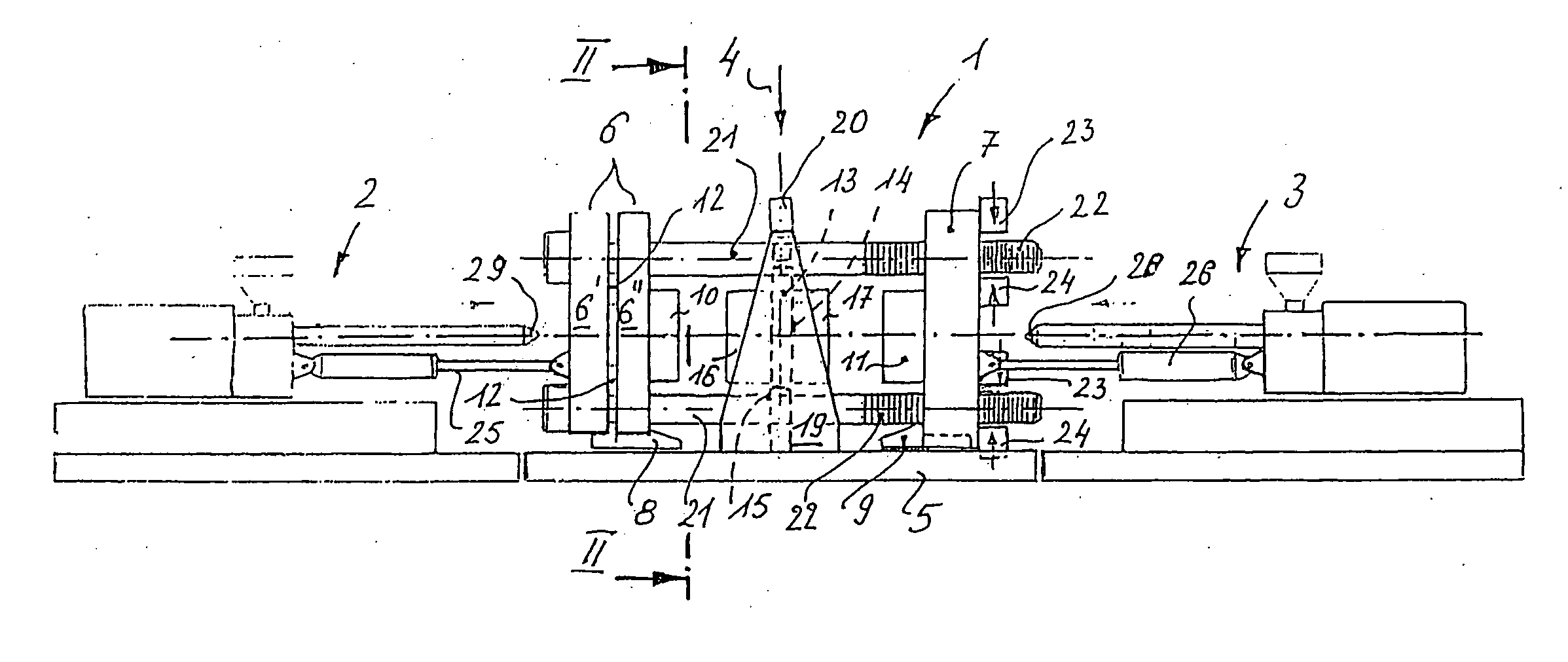
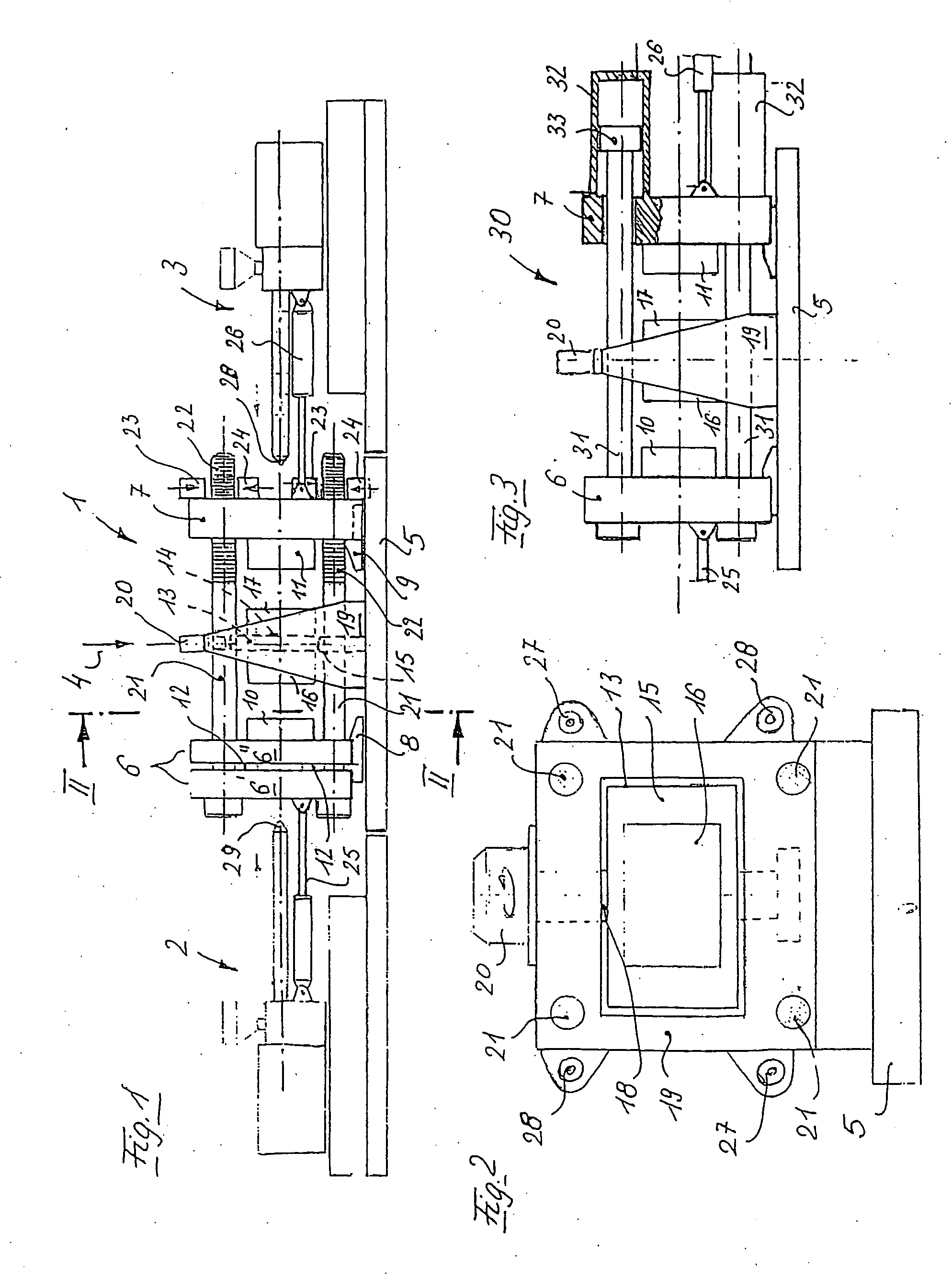
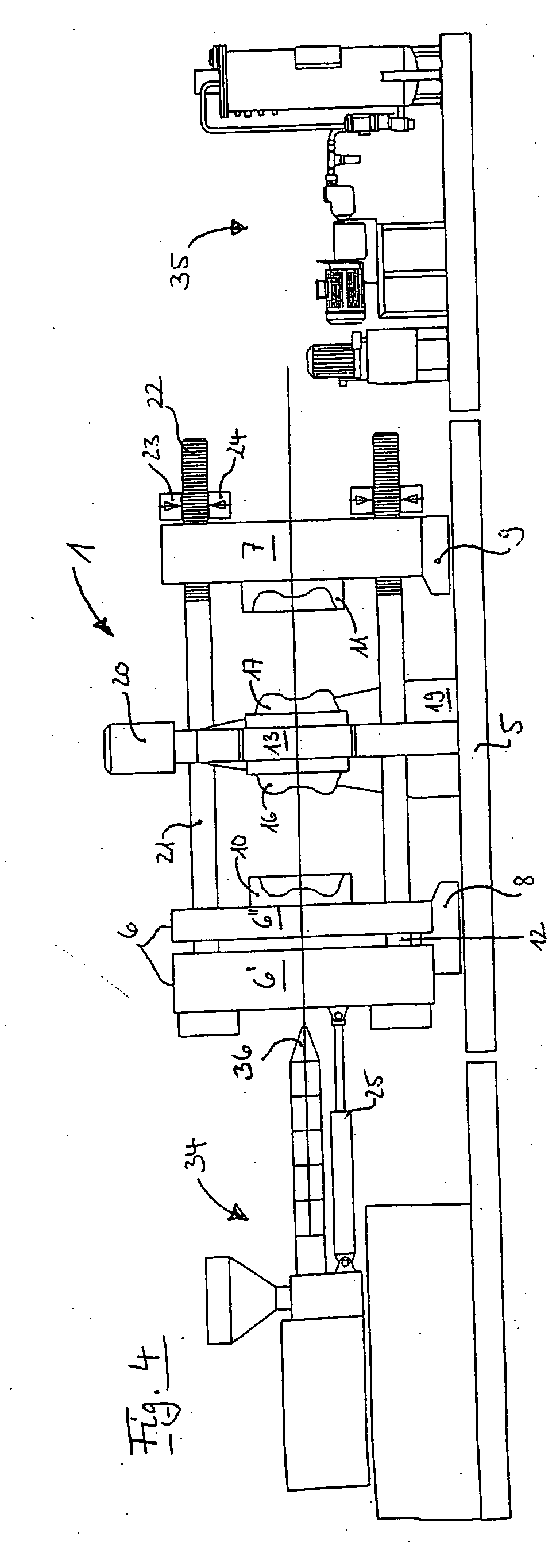
[0032] Turning now to the drawing, and in particular to FIG. 1, there is shown an injection molding machine with a mold closing device 1 and two injection units 2 and 3. Arrow 4 indicates schematically the injection axis of a third optional injection unit which can be provided on the injection molding machine in a so-called T-arrangement.

[0033] The mold closing unit 1 inclu...


PUM

PropertyMeasurementUnit
areasaaaaaaaaaa
structureaaaaaaaaaa
pressureaaaaaaaaaa

Abstract

A mold closing device of an injection molding machine for producing plastic parts made of two or more plastic components includes a central mold carrier element which is arranged between two outer mold mounting plates and has two or four opposing mold mounting areas arranged in pairs for affixing two or four mold halves and which is fitted with a turning device supported in a supporting frame. Each of the mold halves of the mold carrier element can be closed against the mold halves of the outer mold mounting plates by a drive mechanism and a mold pressure unit. The outer mold mounting plates are interconnected by columns which extend through the supporting frame for the central mold carrier element. The supporting frame is fixedly connected to the machine frame while the outer mold mounting plate is displaceably supported on the machine frame.

Description

CROSS-REFERENCES TO RELATED APPLICATIONS [0001] This application is a division of prior filed copending U.S. application Ser. No. 10 / 770,124, filed application Feb. 2, 2004, which is a continuation of prior filed copending PCT International application no. PCT / EP02 / 07985, filed Jul. 18, 2002, which designated the United States and on which priority is claimed under 35 U.S.C. §120, and which claims the priority of German Patent Application, Serial No. 101 38 087.9, filed Aug. 3, 2001, pursuant to 35 U.S.C. 119(a)-(d), the contents of which are incorporated herein by reference.BACKGROUND OF THE INVENTION [0002] The present invention relates to a mold closing device for an injection molding machine, and more particularly to a mold closing device for producing large high-precision multi-component plastic parts. [0003] Mold closing devices are known in the art. For example, British Pat. No. GB 2 300 142 describes a mold closing device, wherein each of the two outer mold mounting plates i...

Claims


Application Information

Patent Timeline
Patent Type & Authority Applications(United States)
IPC IPC(8): B29C45/16B29C45/04B29C45/17B29C67/24
CPCB29C45/045B29C45/1628B29C45/1657B29C45/1671B29C45/1679B29C67/246B29C2045/1631B29C2045/1632B29C2045/326
Inventor WOBBE, HANSWOHLRAB, WALTER
Owner KRAUSSMAFFEI TECH GMBH
Why Eureka
Try Eureka