Tire having an illuminated sidewall

a technology of illuminated sidewalls and tires, which is applied in the direction of tyre sidewalls, vehicle components, transportation and packaging, etc., can solve the problems of only visible reflectors, general inconvenient incorporation into the wheel of the vehicle, and lighting systems

Inactive Publication Date: 2008-05-08
LOSEY ROBERT ALLEN +3
View PDF16 Cites 4 Cited by
  • Summary
  • Abstract
  • Description
  • Claims
  • Application Information

AI Technical Summary

Benefits of technology

[0007]According to a further aspect of the invention, a tire is adapted to receive an electro-luminescent device in a post-cure adhesive attachment by providing a recess in

Problems solved by technology

Such reflectors, however, are only visible within a narrow range of incident light.
Such lighting systems, however, are generally not suitable for incorporation into a wheel of the vehicle due to the size of the incandescent lights, the power requirements needed to power the lighting system, and/or the commuting requirements to provide power to the lighting system.

Method used


Image

  • Tire having an illuminated sidewall
  • Tire having an illuminated sidewall
  • Tire having an illuminated sidewall

Examples


Embodiment Construction

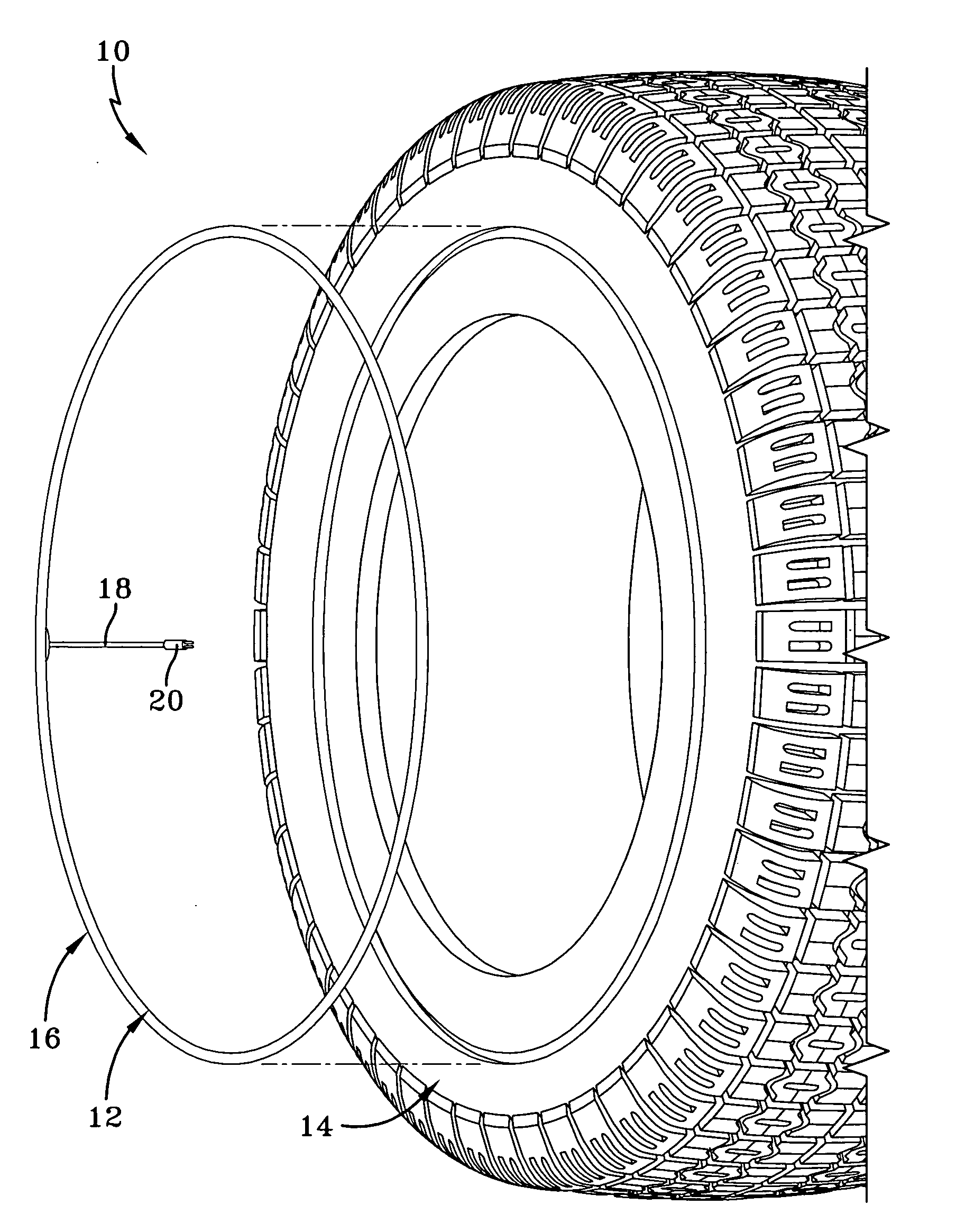
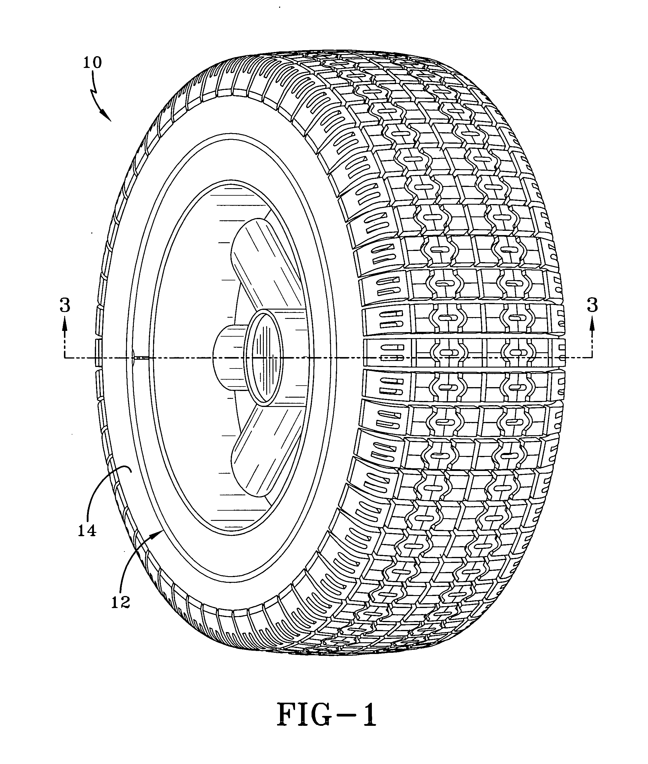
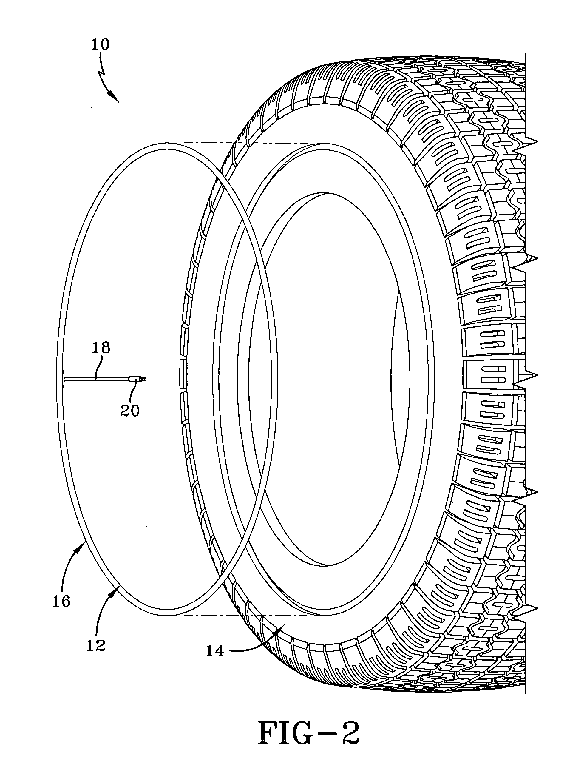
[0016]Referring to FIGS. 1, 2, and 3, a tire 10 is shown having an electro-luminescent device 12 attached to a tire sidewall 14. The device 12 includes a wire 16, electrical conductors 18 coupled to the wire 16, and a terminal electrical connector 20. Wire 16 in device 12 is of a type that glows when powered by compact drivers, giving off light of a particular color. Such assemblies are commercially available, such as from Solution Industries of 1704 Seamist Drive, Houston, Tex. The wire is phosphor coated which emits a light when energized. Different color plastics jackets may surround the phosphor coated wire and be used to change the color of the emitted light. The electro-luminescent medium, while shown in the embodiment of FIGS. 1-3 in the form of a wire 16, is available in a variety of shapes and sizes and may be configured according to the invention as a precut or shaped panel that emits light of various colors when powered.

[0017]Accordingly, device 12 may be affixed to the t...


PUM


Abstract

An electro-luminescent device is affixed to a tire sidewall and powered by a power source affixed to the wheel or tire. Wire(s) within the device in a preferred configuration emit a light in one or more colors in response to energization by the power source. The electro-luminescent display may be energized by appropriate circuit drivers to flash and may be activated to flash with other triggers such as car alarm systems, audio output, car locators, etc.

Description

FIELD OF THE INVENTION[0001]The invention relates generally to an illumination system for a tire and, more specifically, to a tire having a powered illuminated sidewall.BACKGROUND OF THE INVENTION[0002]In various applications, it is desirable to provide illumination to a vehicle wheel for the purpose of safety or to provide a special effect. It is known to utilize reflectors to the wheels of vehicles to make the vehicles more visible. Such reflectors, however, are only visible within a narrow range of incident light. Situated outside of the path of a light source, such devices are not noticeable.[0003]It is further known to use incandescent lights on the exterior of a vehicle to replace reflective devices. Such lighting systems, however, are generally not suitable for incorporation into a wheel of the vehicle due to the size of the incandescent lights, the power requirements needed to power the lighting system, and / or the commuting requirements to provide power to the lighting syste...

Claims


Application Information

Patent Timeline
IPC IPC(8): B60C19/00
CPCB60C13/001
Inventor LOSEY, ROBERT ALLENZHAO, JUNLINGATTINELLO, JOHN STEVENDOWNING, JACKLYN LEE
Owner LOSEY ROBERT ALLEN
Why Eureka
Try Eureka