Input port structure of shredder

Inactive Publication Date: 2008-05-08
CARL JIMUKI
View PDF3 Cites 0 Cited by
  • Summary
  • Abstract
  • Description
  • Claims
  • Application Information

AI Technical Summary

Benefits of technology

[0012]Furthermore, in case the operator's fingers or sheet materials, the thickness of which exceeds cutting capabilities of the shredder, are introduced into the input port, the wall member is displaced so as to spread the passage. The operator can thus easily and instantaneously draw out those disallowed objects, which are about to be drawn into a shredded portion. Here, since the engagement between the wall member and the lock member remains, the passage is restricted to be unduly spread even if the operator's fingers are forcibly inserted into the input port, thereby being able to prevent the fingers from being further inserted toward the shredded cutter.
[0025]As regards the above structure, when the wall member is mounted on the housing body, the passage for the objects can be restricted with two surfaces: the introduction surface and the passage surface. The objects can thus be smoothly introduced into the shredded cutter.

Problems solved by technology

Further, depending on positions in which the proximity sensor is placed, the sensor may mistakenly respond to the operator's hands when he introduces the objects into the input port of the shredder.
This will deteriorate efficiency of cutting operation.
Accordingly, not only the structure of the sensor becomes complicated, but also the operator is confronted with the difficulty of adjusting positions in which the sensor is placed.
These eventually increase manufacturing costs as well as merchandise costs, which brings difficulties to make the merchandise pervaded in a market as household shredders.
However, in case that the operator intends to instantaneously draw out the transited objects from the input port of the shredder, it does not work effectively.
As a result, if the operator fingers are about to be drawn into the interior of the shredder along with the objects, the operator has difficulties to instantaneously draw out his fingers from the input port of the shredder.

Method used


Image

  • Input port structure of shredder
  • Input port structure of shredder
  • Input port structure of shredder

Examples


Embodiment Construction

[0043]Preferred embodiments of the present invention will be described with reference to the accompanying drawings. The embodiments of the present invention will not be limited to the ones hereinafter described, but as long as the problems based on the present invention can be solved, any other embodiments are applicable.

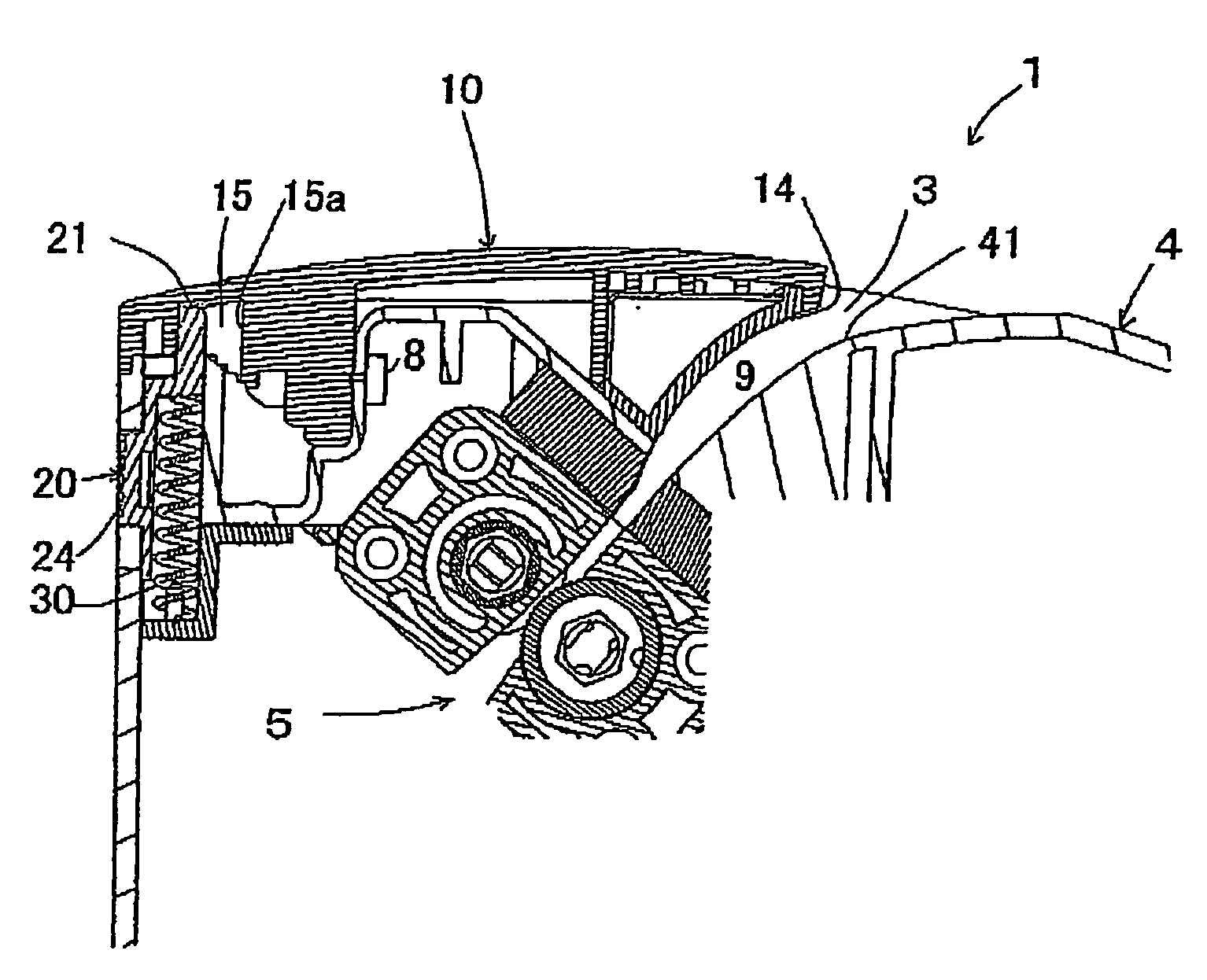
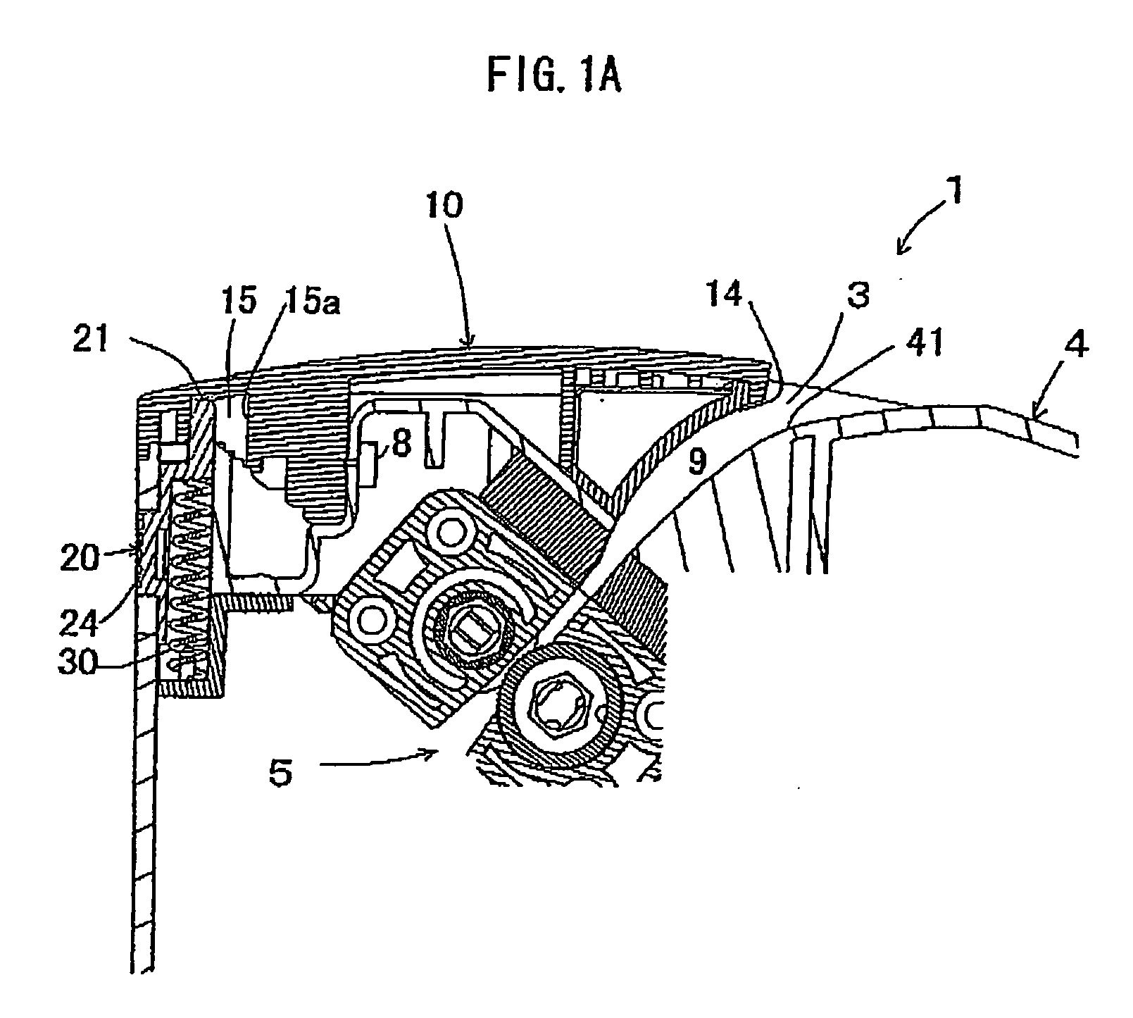
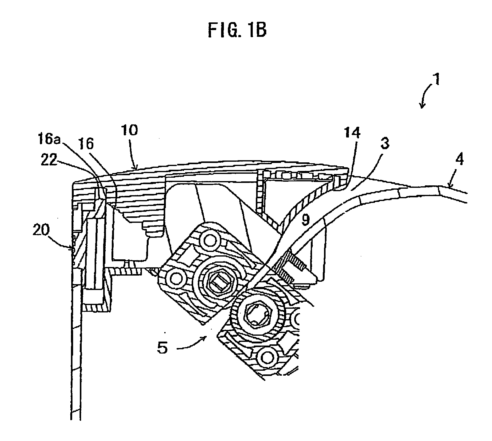
[0044]FIG. 1 shows a cross-sectional view according to the present invention, which indicates input port structure 1 of a shredder. This input port structure 1 is applicable to an input port 3 of a shredder 2 of FIG. 2. FIG. 2 shows the shredder 2 cut at the center thereof in a lateral direction. FIG. 1A is a cross-sectional view mainly introducing the portion of the input port 3 of FIG. 2 while FIG. 1B is a cross-sectional view mainly introducing the shredder 2 of the line A-A of FIG. 2. To begin with, the shredder 2, to which the input port structure 1 according to the present invention is applied, will be explained.

[0045]This shredder 2 shreds sheet-like material...


PUM


Abstract

There is provided an input port structure of a shredder, the shredder comprising: an input port; a wall member including a wall surface directed to the input port; and a lock member that installs the wall member in a housing body, wherein: the wall member and the lock member have either a stepped portion with a plurality of steps or an engaged portion being engaged with the steps of the stepped portion; and by applying given external force to a passage directed to a shredded cutter in a direction to spread the passage relative to the wall member, the steps of the stepped portion engage with the engaged portion while maintaining an engaged condition between the wall member and the lock member.

Description

BACKGROUND OF THE INVENTION[0001]1. Field of the Invention[0002]The present invention relates to input port structure of shredders in which to finely cut sheet materials such as paper, compact discs, etc., and more particularly to input port structure of shredders enabling to pull out objects that should not be allowed for insertion from an input port of a shredder when the disallowed objects are about to be drawn into a cutting portion of the shredder thereby contributing to preventing an occurrence of injuries at the input port.[0003]2. Description of the Related Art[0004]As regards technique in which to prevent an occurrence of injuries caused by mistakenly inserting fingers into an input port of shredders, Japanese Patent Application Laid-Open No. 2005-95898 (hereinafter “reference 1”), for example, discloses the technique that a proximity sensor sensing the existence of persons or animals is provided nearby the input port of the shredders.[0005]In addition, as regards technique...

Claims


Application Information

Patent Timeline
IPC IPC(8): B02C7/11
CPCB02C18/0007B02C2018/168B02C2018/0046B02C18/2291
Inventor ISHIHARA, MUNEYUKI
Owner CARL JIMUKI
Why Eureka
Try Eureka