Distributed temperature sensing in a remotely operated vehicle umbilical fiber optic cable

Active Publication Date: 2008-05-15
WEATHERFORD TECH HLDG LLC
View PDF8 Cites 18 Cited by
  • Summary
  • Abstract
  • Description
  • Claims
  • Application Information

AI Technical Summary

Benefits of technology

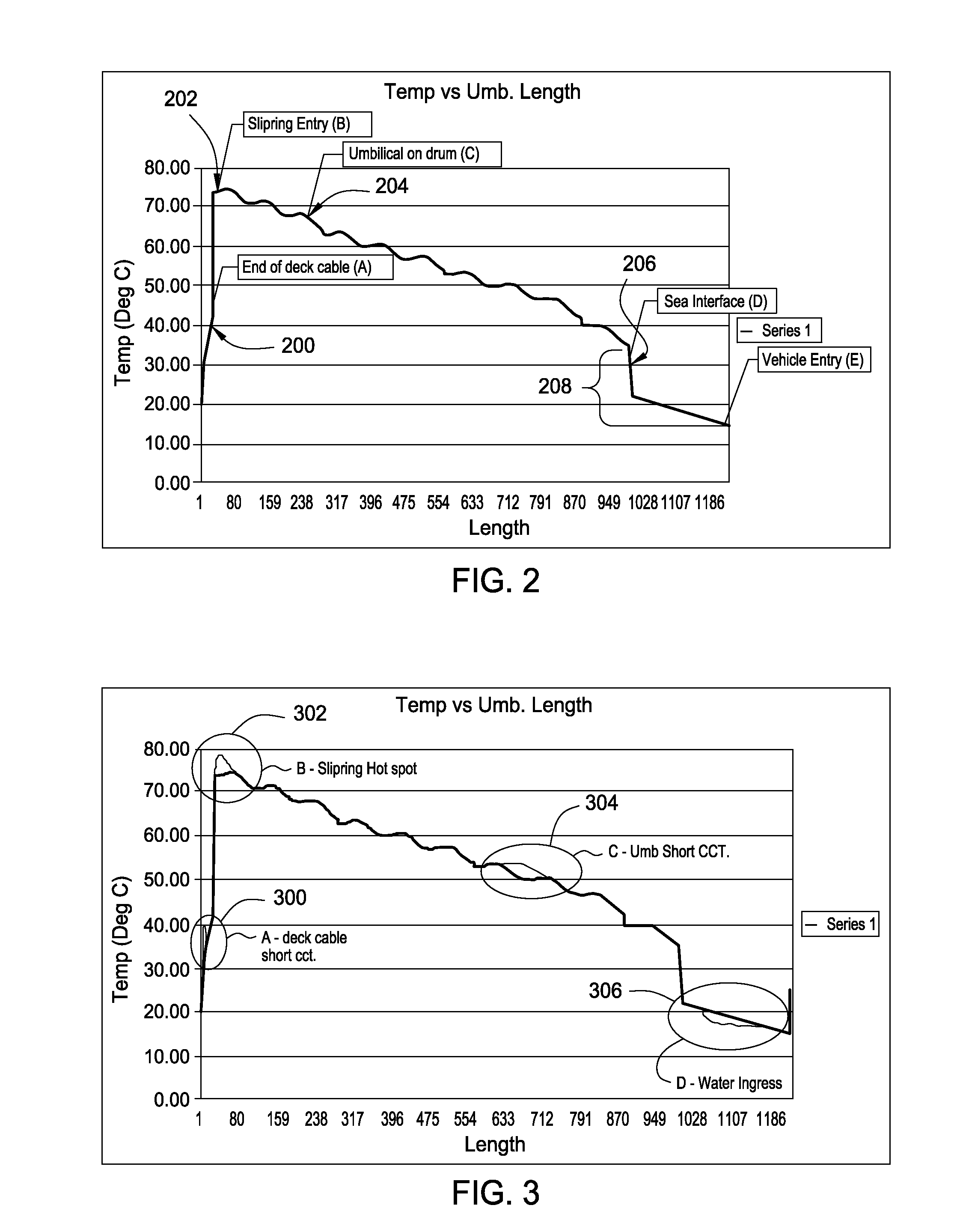
[0007]Recent advances in fiber optic technology have been developed that permit the measurement of temperature along a multi-mode fiber optic cable with no external electronics. Such technology provides the ability for an ROV operator to determine the actual spatial temperature gradient of an umbilical core over the length of the umbilical. The application of such technology allows the ROV operators and systems designers to select and engineer the umbilical with much closer tolerances providing mo

Problems solved by technology

However, the umbilical can create a source for potential failure.
For example, the umbilical can overheat since operators lack any indication as to umbilica

Method used


Image

  • Distributed temperature sensing in a remotely operated vehicle umbilical fiber optic cable
  • Distributed temperature sensing in a remotely operated vehicle umbilical fiber optic cable
  • Distributed temperature sensing in a remotely operated vehicle umbilical fiber optic cable

Examples


Embodiment Construction

[0017]One issue with remotely operated vehicle (ROV) umbilical designs is that the electrical power available to a ROV is ultimately limited by the delivery capability of the umbilical. The umbilical limit constrains the amount of power for the vehicle. Although an umbilical may be sized in theory to provide any level of power, the weight and size of such an umbilical becomes impractical. In practice, any umbilical having a diameter over 43 mm may be considered unfeasible. Furthermore, the cost of an umbilical increases as the copper commodity prices rise. Therefore, limiting the diameter of the umbilical, while maximizing the power supplied to the ROV is critical in the design of the umbilical.

[0018]Some constraints that face an umbilical designer include: power required, weight in water and air, bending radius (and hence maximum diameter), number of additional signals, and length of umbilical required. One of the main factors taken into consideration in a new vehicle design is the...


PUM


Abstract

Methods and apparatus for monitoring a remotely operated vehicle umbilical condition in real time allowing for improving of power delivery as well as early detection of threats to integrity of the umbilical. The umbilical may include an optical fiber. Processing equipment may enable distributed temperature sensing along the optical fiber.

Description

CROSS-REFERENCE TO RELATED APPLICATIONS[0001]This application claims benefit of U.S. provisional patent application Ser. No. 60 / 864,543, filed Nov. 6, 2006, which is herein incorporated by reference in its entirely.BACKGROUND OF THE INVENTION[0002]1. Field of the Invention[0003]Embodiments of the invention generally relate to an umbilical for use with a remotely operated vehicle.[0004]2. Description of the Related Art[0005]A remotely operated vehicle (ROV), such as used in offshore oil / gas exploration / production, utilizes an umbilical to connect to and / or power the vehicle. However, the umbilical can create a source for potential failure. For example, the umbilical can overheat since operators lack any indication as to umbilical core temperatures that occur under loading (e.g., resistive loading and self heating caused by eddy currents in a drum upon which the umbilical is wound). Repeated winding on and off the winch and dynamic changing mechanical tension of the cable may affect a...

Claims


Application Information

Patent Timeline
IPC IPC(8): B63G8/00
CPCB63B21/66G01K11/32B63G8/001
Inventor SMITH, PETER MARK
Owner WEATHERFORD TECH HLDG LLC
Why Eureka
Try Eureka