Food mincer

a technology of food mincer and grater, which is applied in the field of kitchen appliances, can solve the problems of indicia wear off and still has a drawback, and achieve the effect of improving the visual indication of position

Active Publication Date: 2015-05-07
DART IND INC
View PDF4 Cites 0 Cited by
  • Summary
  • Abstract
  • Description
  • Claims
  • Application Information

AI Technical Summary

Benefits of technology

[0005]An object of the present invention is to provide a suction base for countertop

Problems solved by technology

While this is an improvement over other mechanisms for activating a suction plate, it still has a drawback.
Not

Method used


Image

  • Food mincer
  • Food mincer
  • Food mincer

Examples


Embodiment Construction

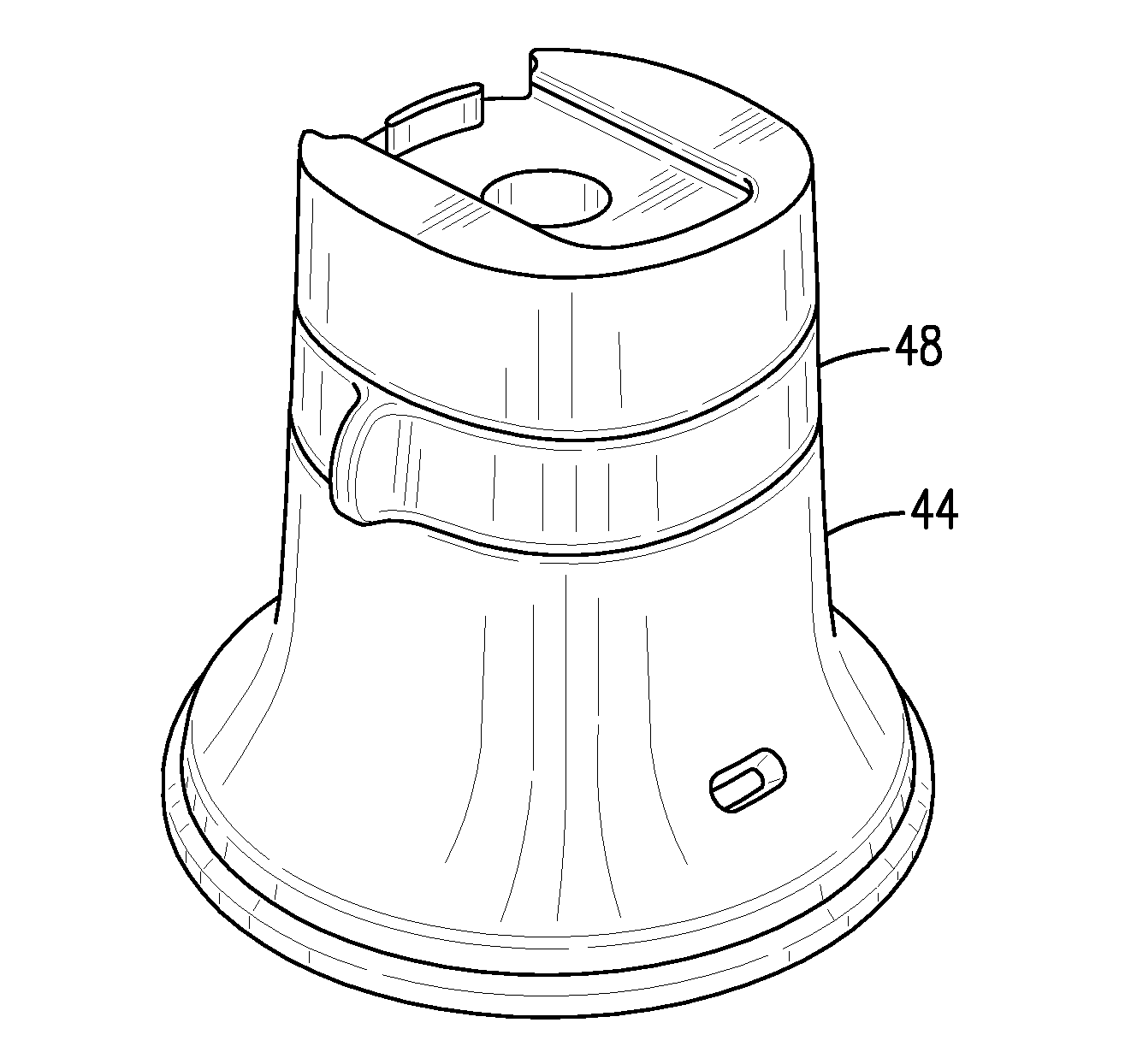
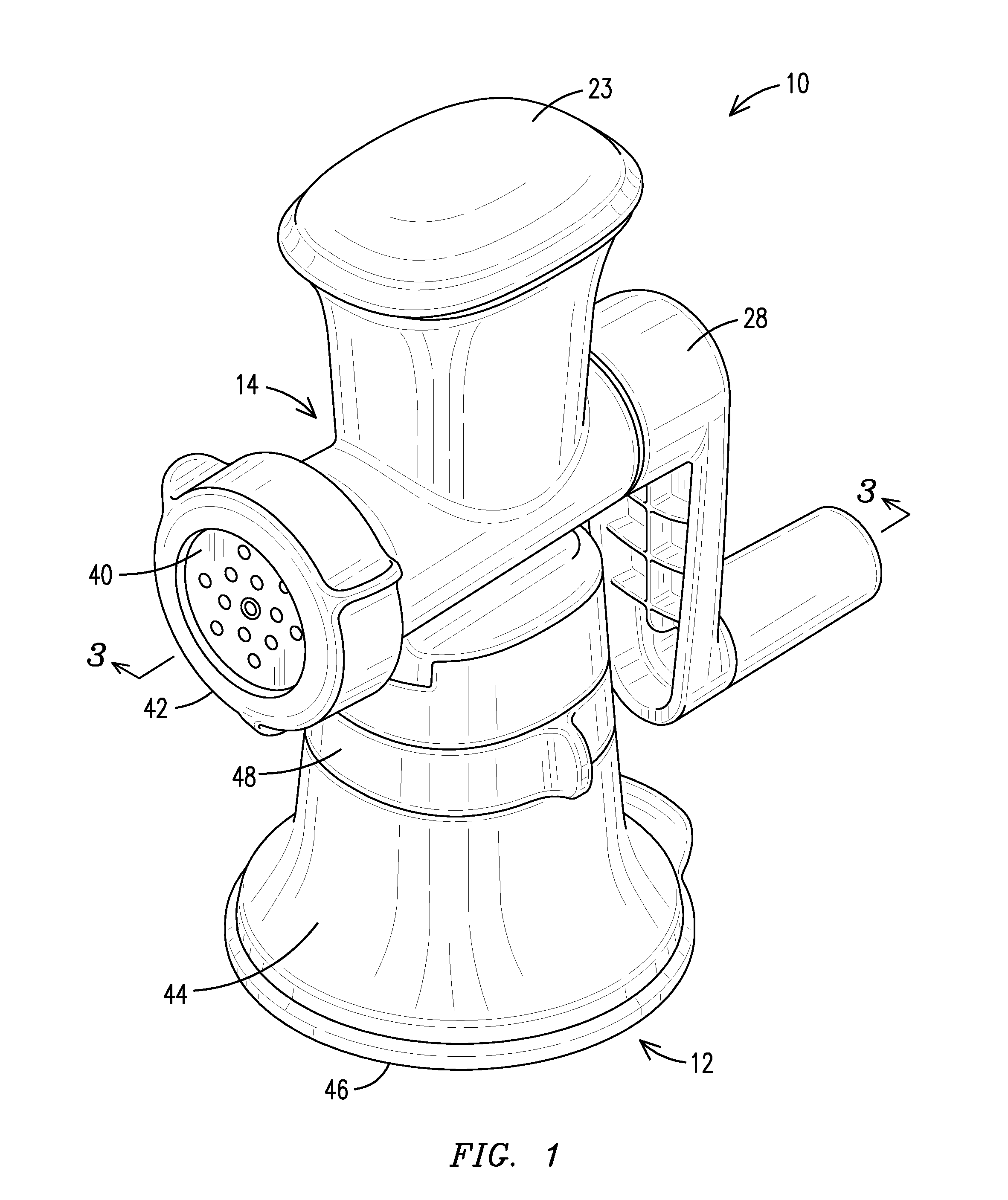
[0020]With reference to FIG. 1, a food mincer according to the present invention is generally designated by reference numeral 10. The food mincer 10 generally includes a suction base 12 and a mincer attachment 14. These two components are both similar in many respects to the base and mincer shown in U.S. Pat. No. 7,207,510 B2 to Yan Kwok Wong which is included herein by reference.

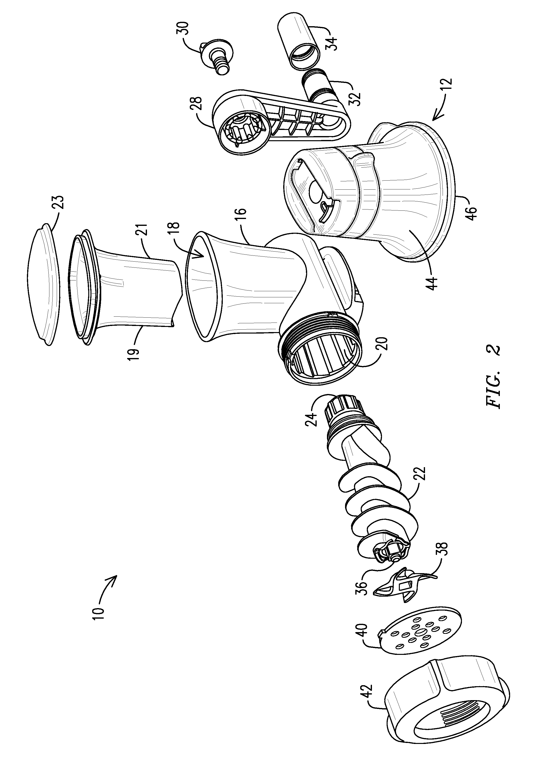
[0021]The mincer assembly 14 includes a main housing 16 having a vertical feed chute 18 leading to a horizontal screw chamber 20. The screw chamber 20 receives a feed screw 22 which includes a splined rear end 24 which extends through a crank aperture 26 (FIG. 3). A crank handle 28 includes at a first end a connector having mating slots to receive the rear end 24, and a handle mounting screw 30 extends through the connector to secure within a threaded opening in the rear end 24. The other end of the crank handle 28 include a projecting rod 32 which will receive a crank sleeve 34 thereover in a snap fit allo...


PUM


Abstract

A food mincer providing improved features. The suction base includes a control ring providing an improved visual indication of its position. The plunger to feed the food is formed as a hollow container having a sealing lid to provide a storage area for accessories. The feed screw is formed in a multi-step molding process to allow for closer tolerances, which in turn allows for a simple gasket seal to be used. The feed screw and fan blade include a mating configuration only when the fan blade is in the proper orientation, such that if the fan blade is assembled in the incorrect orientation the extrusion grids may not be assembled.

Description

CROSS REFERENCE TO RELATED APPLICATIONS[0001]This application is related to co-pending application no. 29471646, and co-pending application no. 29471648 which are both incorporated by reference herein.STATEMENT REGARDING FEDERALLY SPONSORED RESEARCH[0002]Not applicable.BACKGROUND OF THE INVENTION[0003]The present invention relates in general to kitchen appliances, and more particularly food mincers. The food mincer includes a novel plunger which includes a sealed storage area therein. The food mincer includes a novel activation ring for securing the mincer to the countertop. The food mincer also includes a novel screw arrangement permitting a reduction in parts. The food mincer further includes a novel blade fan connection which will ensure proper assembly.[0004]Food mincers for home and light commercial use are well known in the art. An example of such a mincer is illustrated in U.S. Pat. No. 7,207,510 B2 to Yan Kwok Wong. This prior art mincer includes a pedestal which will remova...

Claims


Application Information

Patent Timeline
IPC IPC(8): B02C18/30
CPCB02C18/305A47J45/02F16B47/00F16B2200/95B02C18/30F16B47/006
Inventor BACKAERT, DIMITRI M.C.J.CORNU, JUDICAELDE PAUW, FREDERICK M. N.HUET, BABARA R. M.VANNESTE, MICHIEL G. P. H. E.
Owner DART IND INC
Why Eureka
Try Eureka