Method for manufacturing impact absorber for vehicle

a technology for impact absorbers and vehicles, applied in vehicle components, bumpers, vehicular safety arrangments, etc., can solve the problems of weight increment, bumper reinforcement thickness increase,

Inactive Publication Date: 2008-05-15
AISIN SEIKI KK +1
View PDF12 Cites 17 Cited by
  • Summary
  • Abstract
  • Description
  • Claims
  • Application Information

AI Technical Summary

Problems solved by technology

In JP2846983B, the high tensile steel plate needs to be thick to satisfy strength required for the bumper re

Method used


Image

  • Method for manufacturing impact absorber for vehicle
  • Method for manufacturing impact absorber for vehicle
  • Method for manufacturing impact absorber for vehicle

Examples


Embodiment Construction

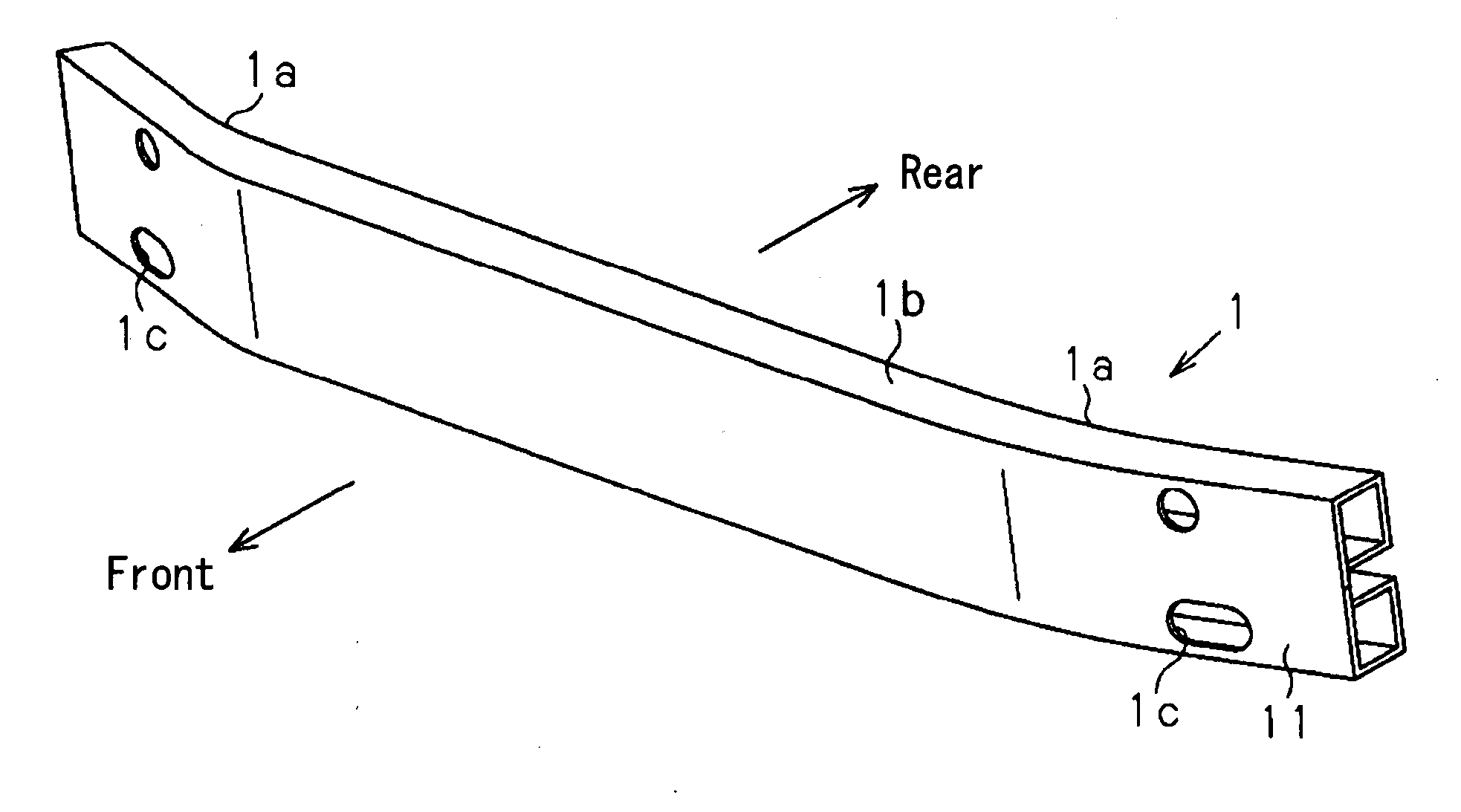
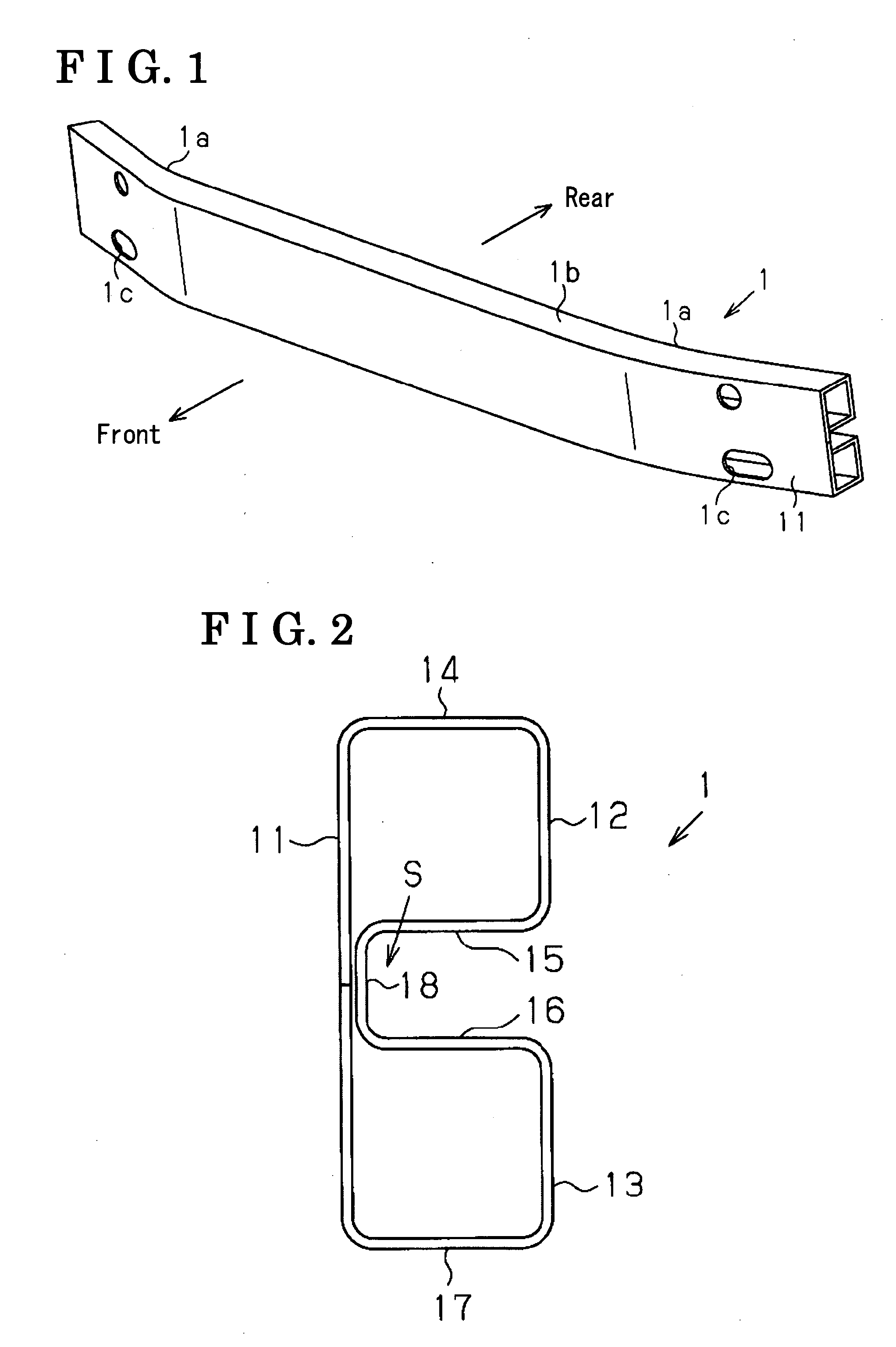
[0017]FIGS. 1 and 2 are a perspective view and a cross section view respectively illustrating a bumper reinforcement 1 manufactured by a manufacturing method for an impact absorber for a vehicle according to the present invention. The bumper reinforcement 1 is adapted for a bumper device to be mounted to a front portion of a vehicle for absorbing impact applied mainly from a front of a vehicle.

[0018]As shown in FIGS. 1 and 2, the bumper reinforcement 1 is made of a band-shaped high tensile steel plate and made into a lengthy, hollow structure. The bumper reinforcement 1 includes a front wall 11 serving as a receiving surface of a load applied from a forward of the vehicle, a pair of rear walls 12, 13 arranged vertically to each other on a mounting surface to the vehicle and parallelly opposing to the front wall 11 respectively, a pair of upper walls 14, 15 connecting the upper rear wall 12 and the front wall 11, and a pair of lower walls 16, 17 connecting the lower rear wall 13 and ...


PUM


Abstract

A method for manufacturing an impact absorber for a vehicle includes a first process for manufacturing a formed body having a constant cross-sectional configuration by performing roll forming on a metal sheet and a second process for manufacturing the impact absorber by performing an induction hardening treatment and a bend forming on the formed body after performing the first process.

Description

CROSS REFERENCE TO RELATED APPLICATIONS[0001]This application is based on and claims priority under 35 U.S.C. § 119 to Japanese Patent Application 2006-305736, filed on Nov. 10, 2006, the entire content of which is incorporated herein by reference.FIELD OF THE INVENTION[0002]This invention generally relates to a method for manufacturing an impact absorber for a vehicle.BACKGROUND[0003]Among related manufacturing methods for impact absorbers for vehicles, for example, a method described in JP2846983B is known. According to the manufacturing method described in JP2846983B, a bumper reinforcement serving as an impact absorber is manufactured by rolling and forming a high tensile steel plate having 450 MPa or higher tensile strength and less than 2.54 mm of thickness so that the formed body has a constant cross sectional configuration in a longitudinal direction thereof, and then by bending the formed body so that the body is formed in an arc-shape (sweep forming) with a constant curvat...

Claims


Application Information

Patent Timeline
IPC IPC(8): B60R19/02
CPCB60R2019/1826B60R19/023B21C37/0803B21C37/155B21C37/157B21D5/086B21D53/88
Inventor HANEDA, SHINICHIKITA, KIYOICHI
Owner AISIN SEIKI KK
Why Eureka
Try Eureka