Battery Pack

a battery pack and battery technology, applied in the field of batteries, can solve the problems of difficult to realize a thickness of about 0.1 mm, deterioration of volume efficiency, and conventional batteries, and achieve the effect of suppressing penetration

Inactive Publication Date: 2007-12-13
SONY CORP
View PDF13 Cites 32 Cited by
  • Summary
  • Abstract
  • Description
  • Claims
  • Application Information

AI Technical Summary

Problems solved by technology

However, the conventional battery pack has the following problems.
There is, consequently, a problem that if such a battery pack is enclosed into a metal can similar to that of the liquid system battery, volume efficiency deteriorates.
It is, therefore, difficult to realize a thickness which is equal to or less than about 0.1 mm only by using the ordinary drawing process.

Method used


Image

  • Battery Pack
  • Battery Pack
  • Battery Pack

Examples


embodiment 1

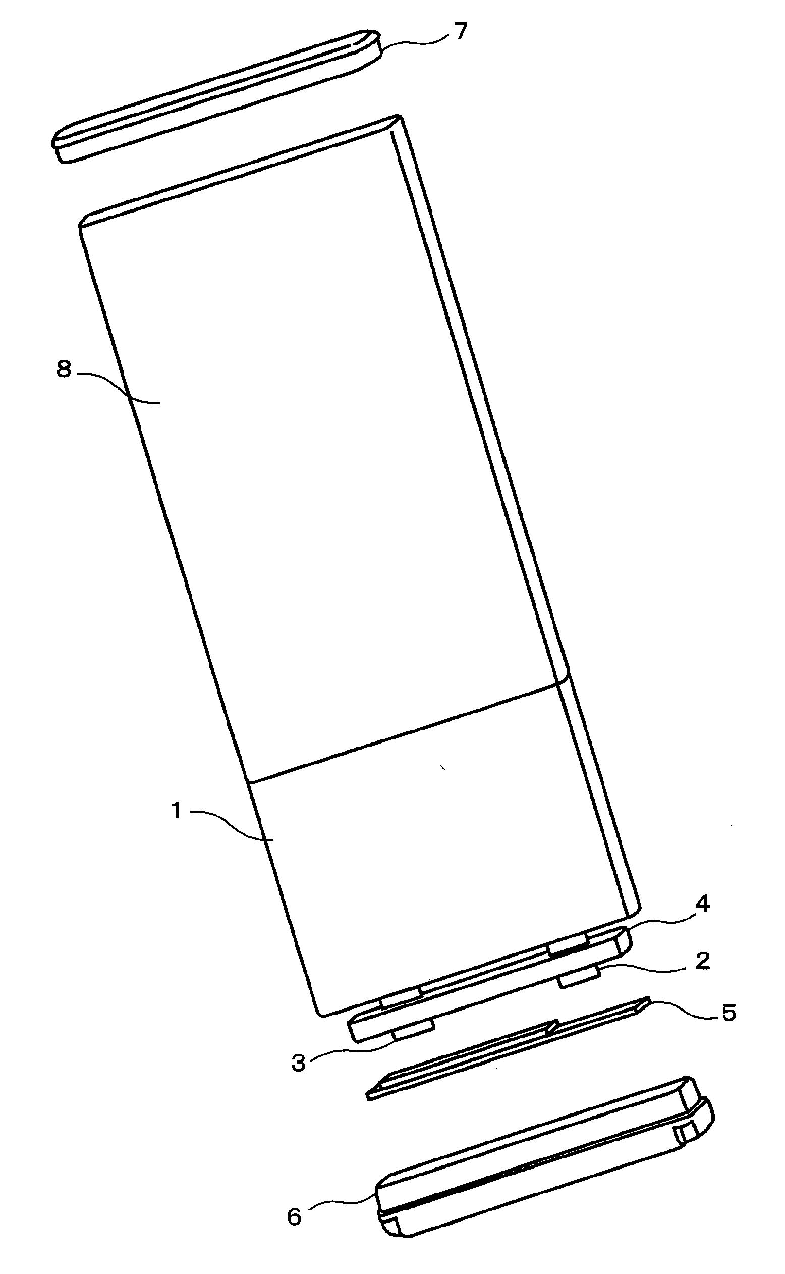
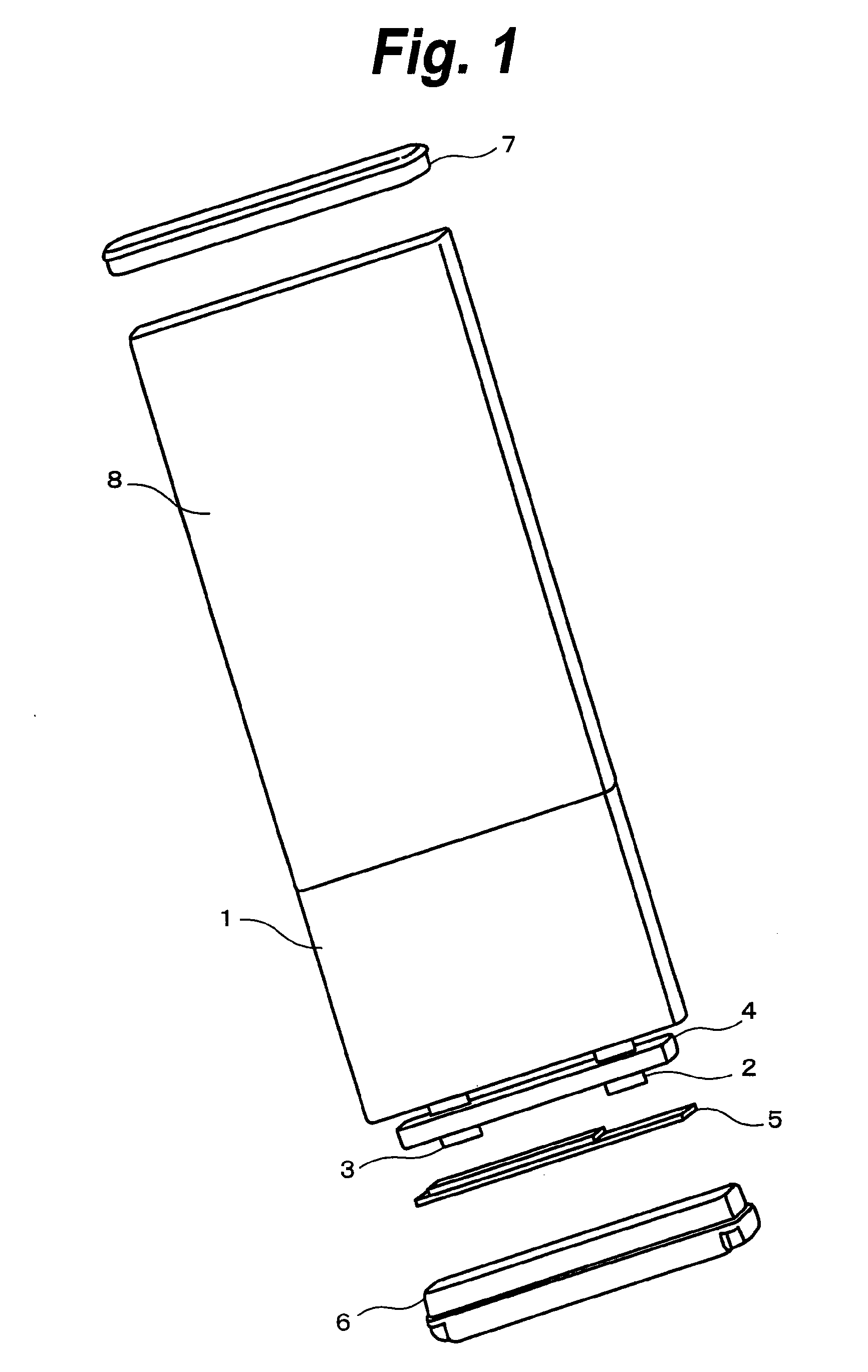
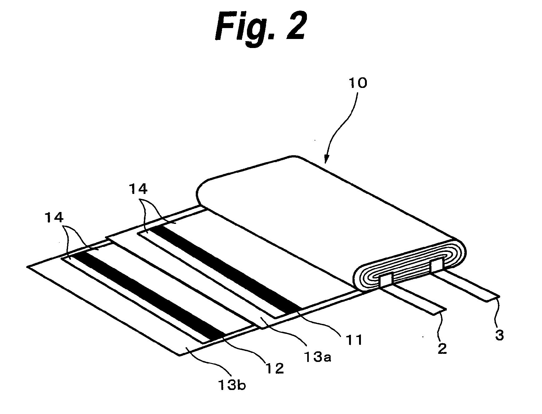
[0091] An assembly in which the circuit board and the like have been connected to a battery cell in which a battery element having a thickness of 4.0 mm has externally been covered with an aluminum laminate having a thickness of 0.1 mm is inserted into a cylindrical collapsed can obtained by molding a cylindrical metal pipe having a thickness of 0.1 mm manufactured by the DI molding method into the rectangular shape, and a front cap and a rear cap formed by the resin molding are fitted to both opening end portions of the cylindrical collapsed can and welded to the outer casing, thereby forming a battery pack.

embodiment 2

[0092] An assembly in which the circuit board and the like have been connected to a battery cell in which a battery element having a thickness of 4.0 mm has externally been covered with an aluminum laminate having a thickness of 0.1 mm is inserted into a cylindrical collapsed can obtained by molding a cylindrical metal pipe having a thickness of 0.1 mm manufactured by the roll forming method into the rectangular shape, and the front cap and the rear cap formed by the resin molding are fitted to both opening end portions of the cylindrical collapsed can and welded to the outer casing, thereby forming a battery pack.

embodiment 3

[0093] An assembly in which a battery element having a thickness of 4.0 mm to which the circuit board and the like have been connected is externally covered with a complex film having a thickness of 0.05 mm is inserted into a cylindrical collapsed can obtained by molding a cylindrical metal pipe having a thickness of 0.1 mm manufactured by the DI molding method into the rectangular shape, and the front cap and the rear cap formed by the resin molding are fitted to both opening end portions of the cylindrical collapsed can and welded to the outer casing, thereby forming a battery pack.


PUM

PropertyMeasurementUnit
thicknessaaaaaaaaaa
thicknessaaaaaaaaaa
thicknessaaaaaaaaaa

Abstract

By using a DI molding method or a roll forming method, a casing member made of a thin cylindrical metal pipe is formed and molded so as to almost coincide with a shape of a battery element, thereby forming an outer casing. A power generating element to which a circuit board has been connected is enclosed in the outer casing and opening portions of the outer casing are closed by a front cap and a rear cap formed by, for example, a resin molding, thereby forming a battery pack. The power generating element is used by externally covering the battery element with a laminate film or the battery element is enclosed as it is into the outer casing. To suppress the penetration of the moisture into the battery, it is also possible to mix a moisture trapper for absorbing the moisture into a resin material of the front cap and rear cap and suppress the penetration of the moisture.

Description

TECHNICAL FIELD [0001] The invention relates to a battery pack which is suitable when it is applied to, for example, a rectangular polymer battery. BACKGROUND ART [0002] In recent years, portable electronic apparatuses such as notebook-sized personal computer, cellular phone, PDA (Personal Digital Assistants), and the like have been spread, and lithium ion batteries having advantages such as high voltage, high energy density, and light weight are widely used as power sources. [0003] Further, as a countermeasure for a liquid leakage which becomes a problem in the case of using a liquid system electrolytic solution, for example, a lithium ion polymer secondary battery in which a gel high polymer film obtained by impregnating a non-aqueous electrolytic solution into polymer or a total solid electrolyte is used as an electrolyte has been put into practical use. [0004] The lithium ion polymer secondary battery has a construction of a battery cell in that a battery element which has a pos...

Claims


Application Information

Patent Timeline
Patent Type & Authority Applications(United States)
IPC IPC(8): H01M2/10B21D51/52H01M50/202H01M50/224H01M50/227H01M50/231H01M50/236H01M50/276H01M50/278H01M50/28H01M50/287
CPCB21D51/52Y10T29/4911H01M2/1022H01M2/08Y02E60/10H01M50/278H01M50/224H01M50/236H01M50/231H01M50/276H01M50/202H01M50/28H01M50/287H01M50/227
Inventor HIRATSUKA, MASARUSAKAMOTO, MITSUOHATTA, KAZUHITOTSUCHIYA, KENJISEGAWA, KENSATO, MASATOICHIHASHI, AKIRAHONDA, KAZUO
Owner SONY CORP
Why Eureka
Try Eureka