
Insulation device for linear motor

a technology of insulation paper and linear motor, which is applied in the direction of dynamo-electric machines, electrical apparatus, windings, etc., can solve the problems of insufficient insulation paper, inconvenient assembly, and inability to properly protect the insulation paper, so as to prevent short circuits and save human labor. , simple and rapid assembly

Active Publication Date: 2008-05-15
HIWIN MIKROSYST
View PDF2 Cites 10 Cited by
  • Summary
  • Abstract
  • Description
  • Claims
  • Application Information

AI Technical Summary

Benefits of technology

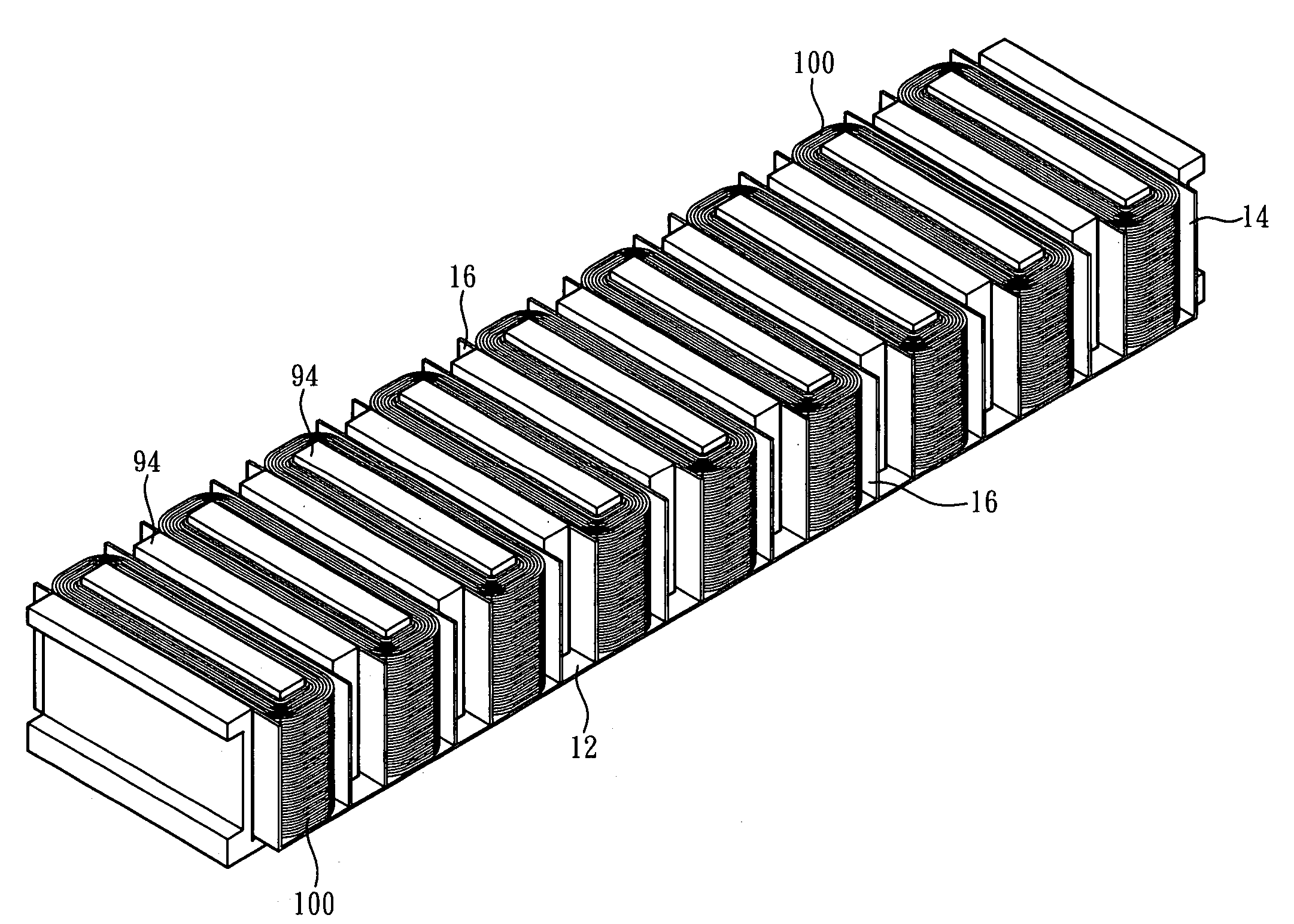
The present invention is a modulized insulation device for a linear motor. The device provides effective insulation between the iron core and coil windings, helps prevent short circuiting, and is easy to assemble and save human labor. It can also be securely positioned on the iron core, increasing processing efficiency.

Problems solved by technology

However, such conventional insulation treatment may be deficient by following reasons.
1. The entire insulation treatment has to be operated manually and respectively for every single tooth of the iron core, and such work can consume enormous human labor.
2. As it is difficult to make an insulation papers used in prior art positioned properly during wrapping the iron coil with the coil winding, the wrapping operation must be conducted with greatest attention and any slight mistake may cause malposition of the insulation papers.
Thus, the processing efficiency of the insulation treatment is substantially limited.

Method used


Image

  • Insulation device for linear motor
  • Insulation device for linear motor
  • Insulation device for linear motor

Examples


Embodiment Construction

[0018]Please refer to FIGS. 1 to 5, which describe a preferred embodiment of the present invention. It is to be understood that the recited figures and embodiment are for illustrating and not intended to limit the structure of the present invention.

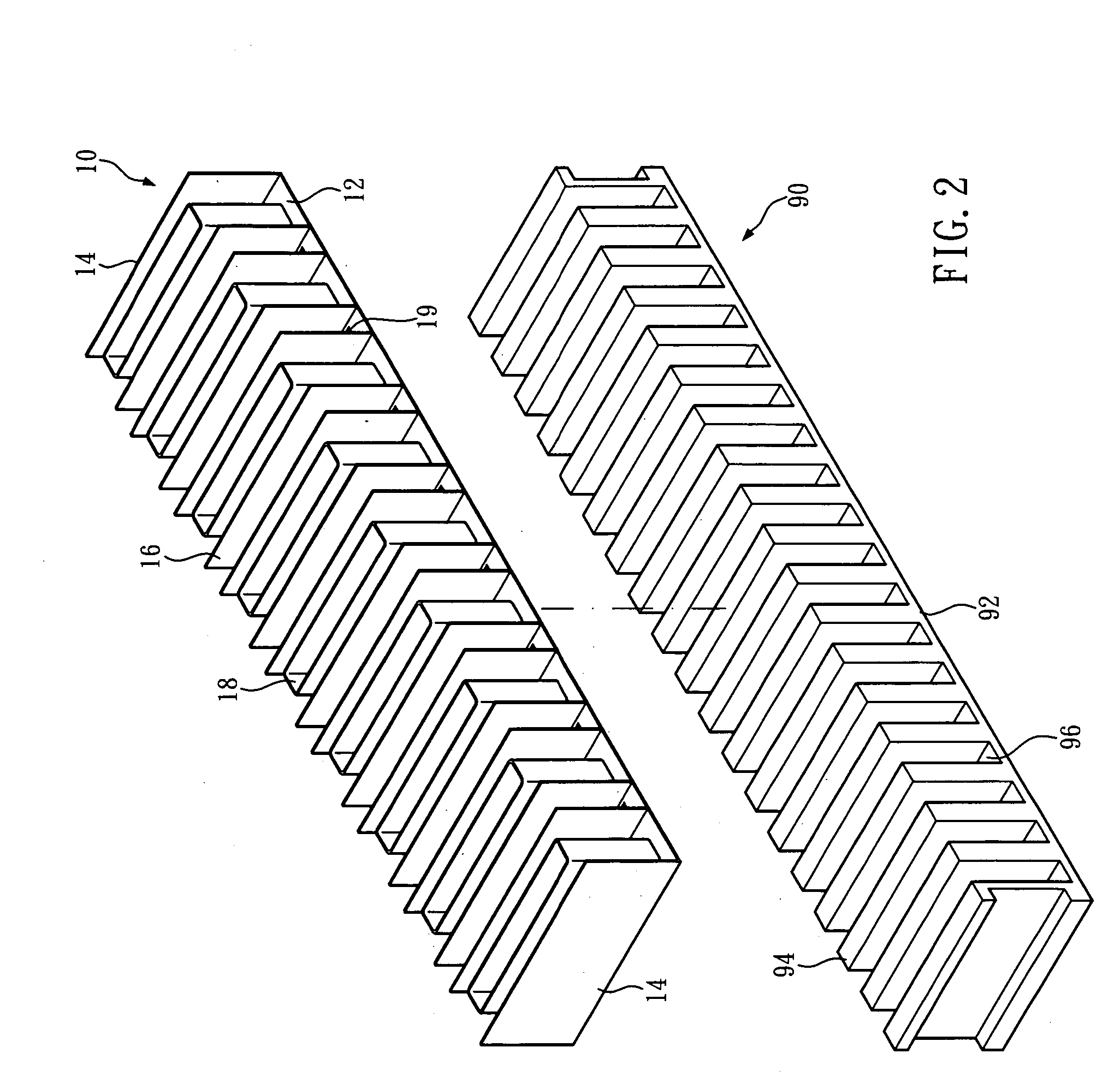
[0019]Referring to FIG. 2, as described above, a iron core 90 of a linear motor is typically made by laminating silicon steel sheets integratedly to form an appearance that comprises a base portion 92 whereon a plurality of teeth 94 and indentations 96 are alternatively aligned.

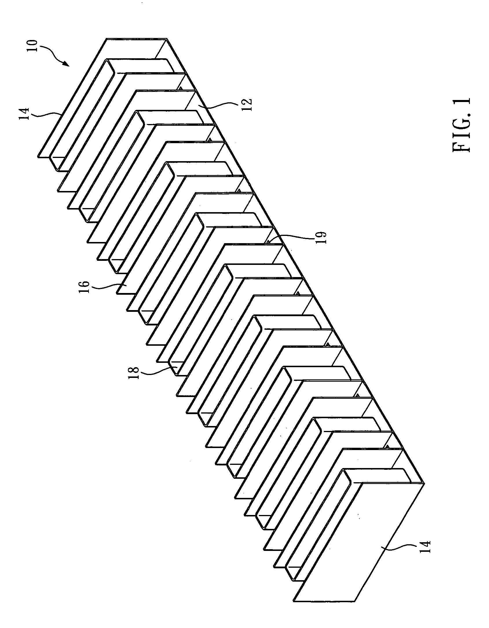
[0020]Accordingly, the disclosed insulation device, as shown in FIGS. 1 and 2, is made through molding a sheet insulation material into an insulation module 10 with the shape harmonized with the shape of an iron core 90 of a linear motor with any known plastic forming technology. In one embodiment of the present invention, the insulation device is formed by means of technology of vacuum tray as a integrated insulation module 10 which comprises a baseplate 12, a pai...


PUM

PropertyMeasurementUnit
shapeaaaaaaaaaa
width dimensionaaaaaaaaaa
processing efficiencyaaaaaaaaaa

Abstract

An insulation device for being assembled in a linear motor is primarily made through molding a sheet insulation material into an insulation module with the shape harmonized with the shape of an iron core of a linear motor. Thus, coil wildings can be indirectly wrapped around the iron core with the insulation module positioned intermediately and thereby a linear motor with perfect insulation treatment between the iron and coil windings is achieved.

Description

BACKGROUND OF THE INVENTION[0001]1. Technical Field[0002]The present invention relates to linear motors, and more particularly, to an insulation device for being assembled in a linear motor to keep the iron core insulated from the coil windings thereof.[0003]2. Description of Related Art[0004]As can be seen in FIG. 2, an iron core 90 constitutes the principal part of a forcer of a linear motor. Such an iron core 90 is typically made by laminating silicon steel sheets integratedly to form an appearance that comprises a base portion 92 whereon a plurality of teeth 94 and indentations 96 are alternatively aligned. To accomplish the iron core 90, a coil winding is further provided to encircle the teeth 94 while being accommodated in the indentations 96. Between the iron core 90 and coil winding, proper insulation treatment is essential to prevent short circuiting or interference between the iron core 90 and coil winding.[0005]In prior art, insulation treatment is practiced by inserting ...

Claims


Application Information

Patent Timeline
Patent Type & Authority Applications(United States)
IPC IPC(8): H02K3/48H02K15/00
CPCH02K3/325Y10T29/49009H02K41/02
Inventor HUANG, LIEH-FENGCHANG, CHIA-MING
Owner HIWIN MIKROSYST
Learn More