
Crosstalk reduction in a crosspoint thyristor switching array using a shielded dielectric stack

a technology of shielded dielectric stack and switching array, which is applied in the direction of basic electric elements, transistors, waveguide devices, etc., can solve the problems of increasing signal insertion loss and difficulty in reducing the thickness of gaas substrates sufficiently, and achieve the effect of preventing short circuiting

Inactive Publication Date: 2005-02-01
TERABURST NETWORKS
View PDF4 Cites 0 Cited by
  • Summary
  • Abstract
  • Description
  • Claims
  • Application Information

AI Technical Summary

Benefits of technology

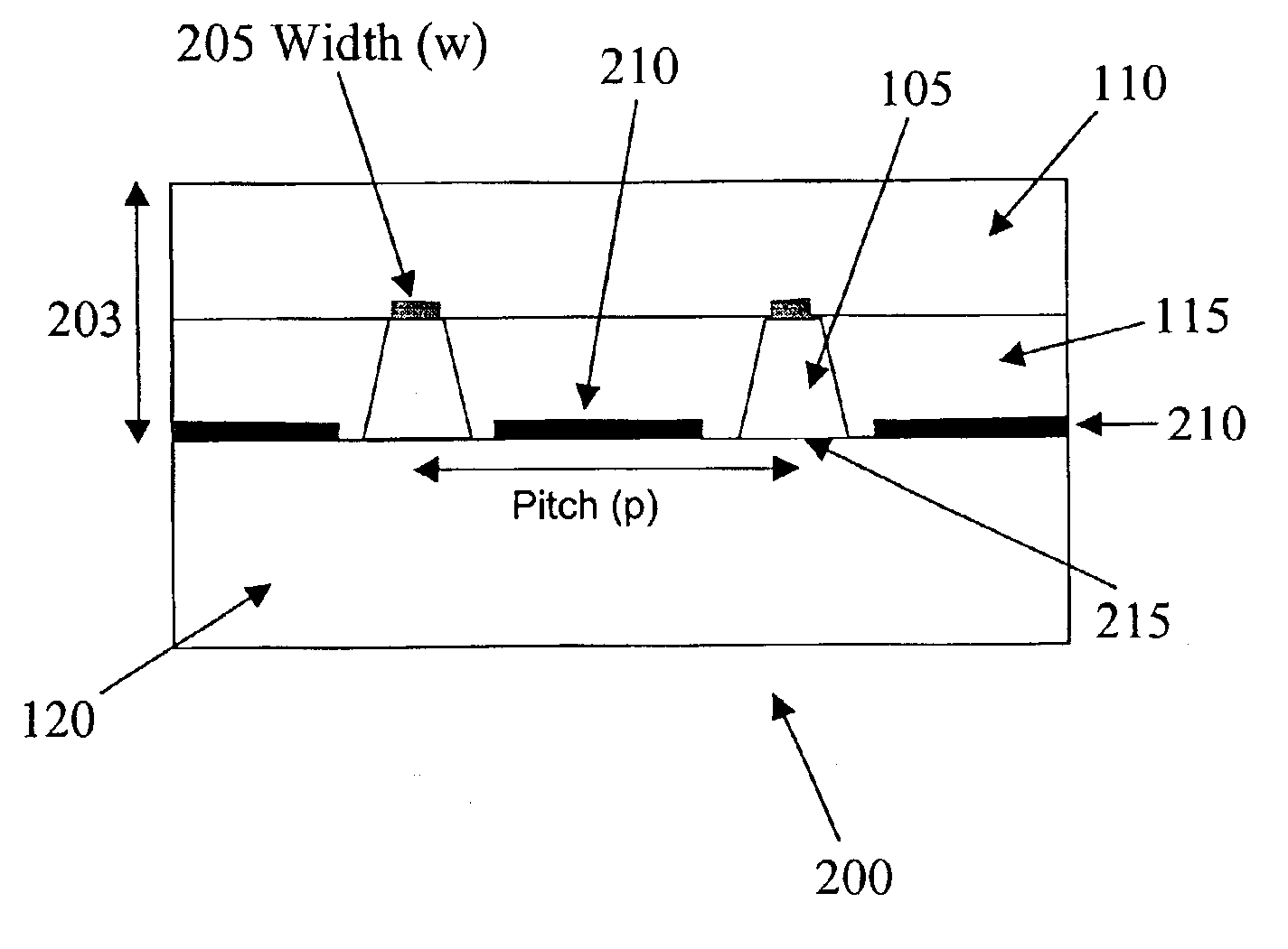
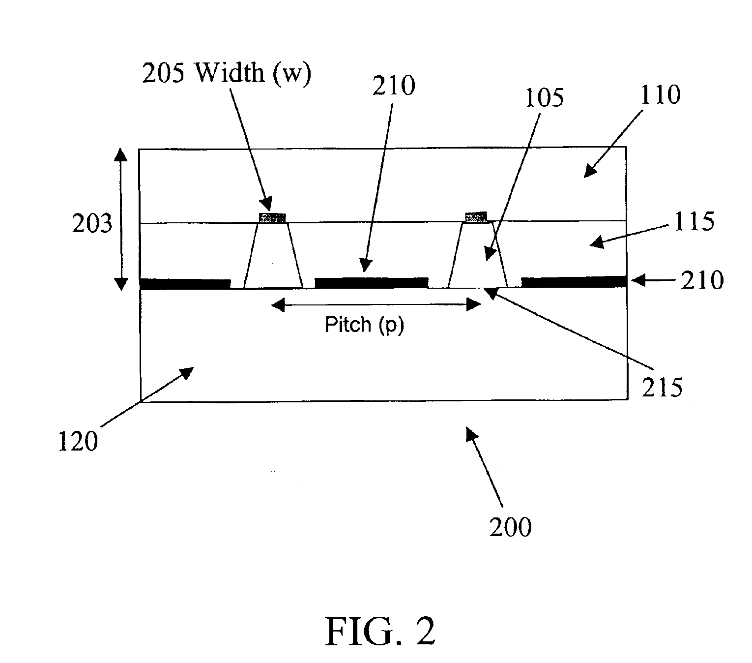
Each of the plurality of thyristor switches can be positioned inside one of the plurality of apertures, such that short circuiting between the plurality of thyristor switches and the first ground plane is prevented. According to an exemplary embodiment, the top of each of the plurality of thyristor switches can be in electrical contact with one of the plurality of signal transmission lines arranged in rows that intersects at the associated intersection point, and the bottom of each of the plurality of thyristor switches can be in electrical contact with one of the plurality of signal transmission lines arranged in columns that intersects at the associated intersection point. According to an alternative exemplary embodiment, the top of each of the plurality of thyristor switches can be in electrical contact with one of the plurality of signal transmission lines arranged in columns that intersects at the associated intersection point, and the bottom of each of the plurality of thyristor switches can be in electrical contact with one of the plurality of signal transmission lines arranged in rows that intersects at the associated intersection point.
The step of associating each of the plurality of thyristor switches with one of the plurality of apertures can include the step of preventing short circuiting between the plurality of thyristor switches and the first ground plane by positioning each of the plurality of thyristor switches inside one of the plurality of apertures. According to an exemplary embodiment, the step of placing each of the plurality of thyristor switches into electrical contact with the signal transmission lines that intersect at the associated intersection point can include the steps of placing the top of each of the plurality of thyristor switches into electrical contact with one of the plurality of signal transmission lines arranged in rows that intersects at the associated intersection point, and placing the bottom of each of the plurality of thyristor switches into electrical contact with one of the plurality of signal transmission lines arranged in columns that intersects at the associated intersection point.

Problems solved by technology

This has the disadvantage, however, of increasing signal insertion loss, because of the increased ohmic losses of the traces, as well as leading to problems with fabrication.
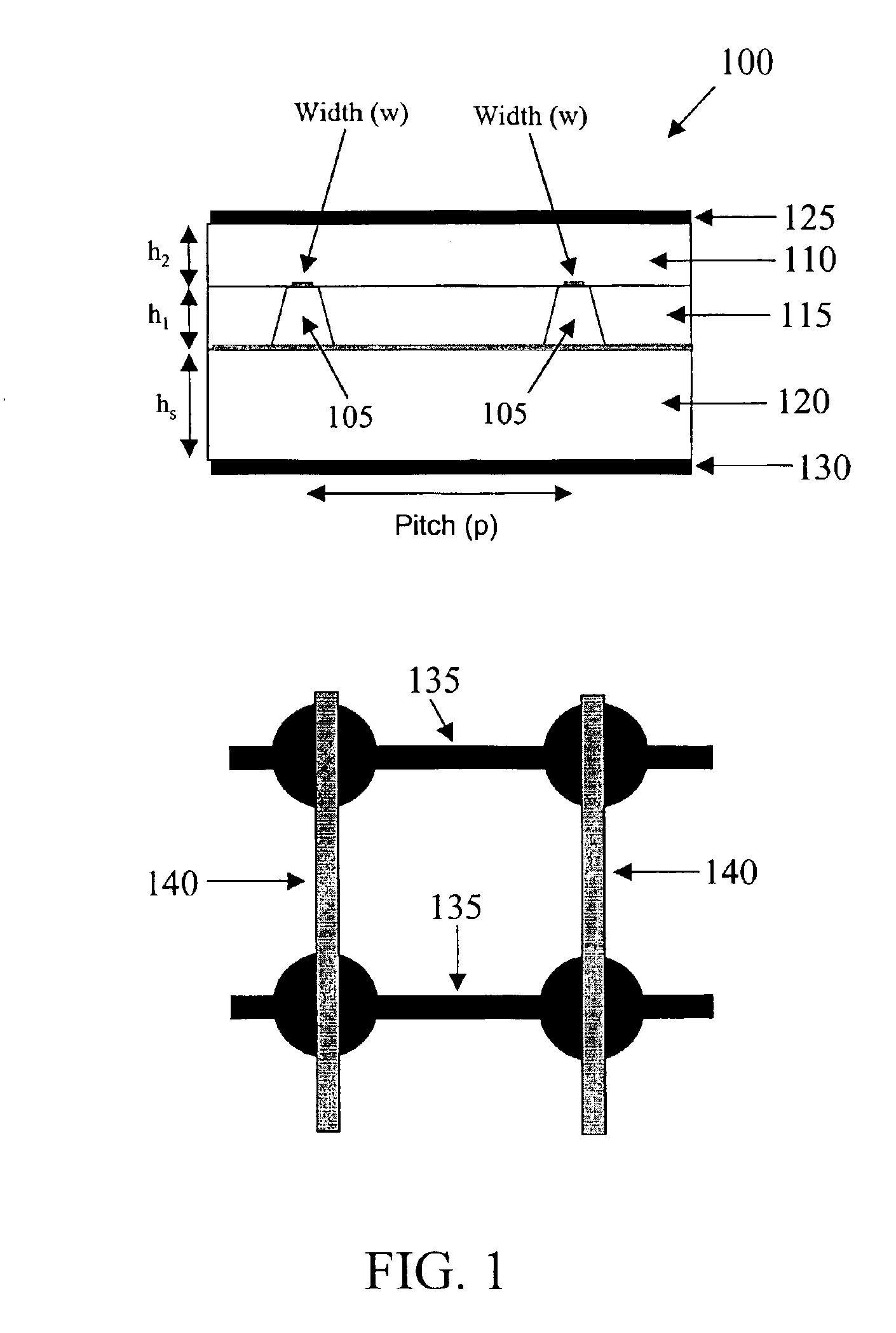
However, in practice, it is difficult to reduce the thickness of the GaAs substrate sufficiently to where its thickness hs is small compared to that of the dielectric layer thicknesses h1 and h2 (e.g., 10 μm).

Method used


Image

  • Crosstalk reduction in a crosspoint thyristor switching array using a shielded dielectric stack
  • Crosstalk reduction in a crosspoint thyristor switching array using a shielded dielectric stack
  • Crosstalk reduction in a crosspoint thyristor switching array using a shielded dielectric stack

Examples


Embodiment Construction

A method and apparatus are disclosed for reducing crosstalk and dispersion in a crosspoint monolithic microwave integrated circuit (MMIC) switch array operating in a range between DC and microwave frequencies. In accordance with an exemplary embodiment, the crosspoint MMIC switch array includes a dielectric stack, a substrate, a first ground plane, a plurality of thyristor switches, a plurality of signal transmission lines arranged in rows; and a plurality of signal transmission lines arranged in columns. The plurality of signal transmission lines arranged in columns intersect the plurality of signal transmission lines arranged in rows at a plurality of intersection points. Each of the plurality of thyristor switches is associated with one of the plurality of intersection points. Each of the plurality of thyristor switches is in electrical contact with the signal transmission lines that intersect at the associated intersection point. Each of the plurality of thyristor switches is lo...


PUM


Abstract

A method and apparatus are disclosed for reducing crosstalk and dispersion in a crosspoint monolithic microwave integrated circuit (MMIC) switch array operating in a range between DC and microwave frequencies. In accordance with an exemplary embodiment, the crosspoint MMIC switch array includes a dielectric stack, a substrate, a first ground plane, a plurality of thyristor switches, a plurality of signal transmission lines arranged in rows; and a plurality of signal transmission lines arranged in columns. The plurality of signal transmission lines arranged in columns intersect the plurality of signal transmission lines arranged in rows at a plurality of intersection points. Each of the plurality of thyristor switches is associated with one of the plurality of intersection points. Each of the plurality of thyristor switches is in electrical contact with the signal transmission lines that intersect at the associated intersection point.

Description

BACKGROUND1. Field of the InventionThe present invention relates to switching arrays used for frequencies in a range between DC and microwave. More particularly, the present invention relates to an apparatus and a method for reducing crosstalk and dispersion in a crosspoint monolithic microwave integrated circuit (MMIC) switch array.2. Background InformationReferring to FIG. 1, a crosspoint monolithic microwave integrated circuit (MMIC) switch array 100 includes thyristor switches 105, an upper dielectric layer 110 and a lower dielectric layer 115, with the lower dielectric layer 115 being positioned upon a substrate 120. Planar connections are made to the upper and lower levels of each thyristor 105. The substrate 120 is made from a semiconductor material, such as gallium arsenide (GaAs). The array is bounded above by an upper ground plane 125 and below by a lower ground plane 130. An example of such a crosspoint MMIC switch array is described in, for example, U.S. patent applicati...

Claims


Application Information

Patent Timeline
IPC IPC(8): H01L29/74H01L29/66H01L31/111H01L31/101H01L29/80H01LH01L23/522H01L27/102H01P1/15
CPCH01L23/5225H01L27/1027H01P1/15H01L2924/3011H01L2924/0002H01L2924/00
Inventor LA RUE, ROSS A.LEVINE, JULES D.CURCIO, DANIELBOLES, TIMOTHYGOODRICH, JOELHOAG, DAVIDKINAYMAN, NOYAN
Owner TERABURST NETWORKS
Learn More