Guide track for track-based vehicle, and traffic system
Active Publication Date: 2013-05-23
MITSUBISHI HEAVY IND ENG LTD
View PDF4 Cites 13 Cited by
Summary
Abstract
Description
Claims
Application Information
AI Technical Summary
This helps you quickly interpret patents by identifying the three key elements:
Problems solved by technology
Method used
Benefits of technology
Benefits of technology
The guide track and transportation system in this patent text is designed to prevent short circuits between conductor rails. This is accomplished by placing a guide wheel in the guide groove of the track main body and providing a conductor rail outside the guide wheel via the support portion. Additionally, a protective member is added to the conductor rail to secure the required insulation distance and protect it from short circuits. This prevents short circuits from occurring between the conductor rails and other structural members.
Problems solved by technology
For this reason, a cross-sectional area for forming the track increases, and when there is a tunnel portion or the like, enormous costs may be incurred.
Method used
Image
Click on the blue label to locate the original text in one second.
Reading with bidirectional positioning of images and text.
Examples
first embodiment
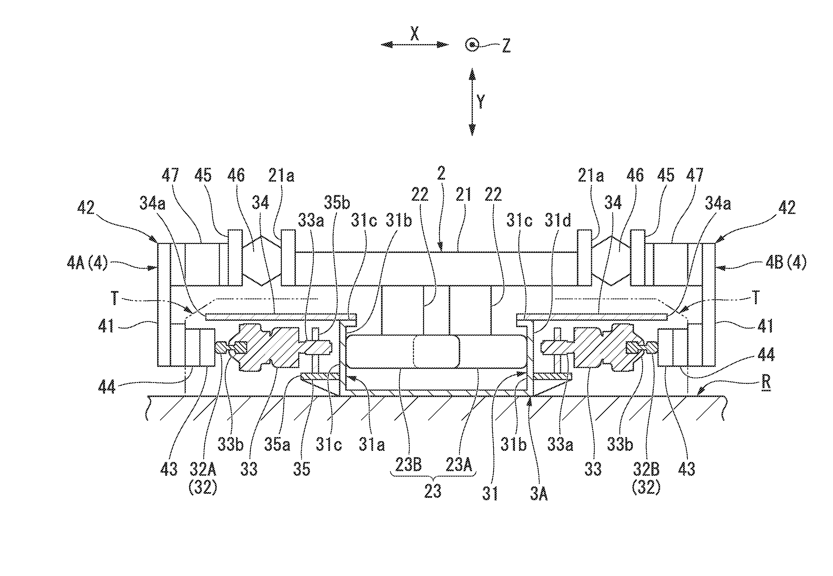
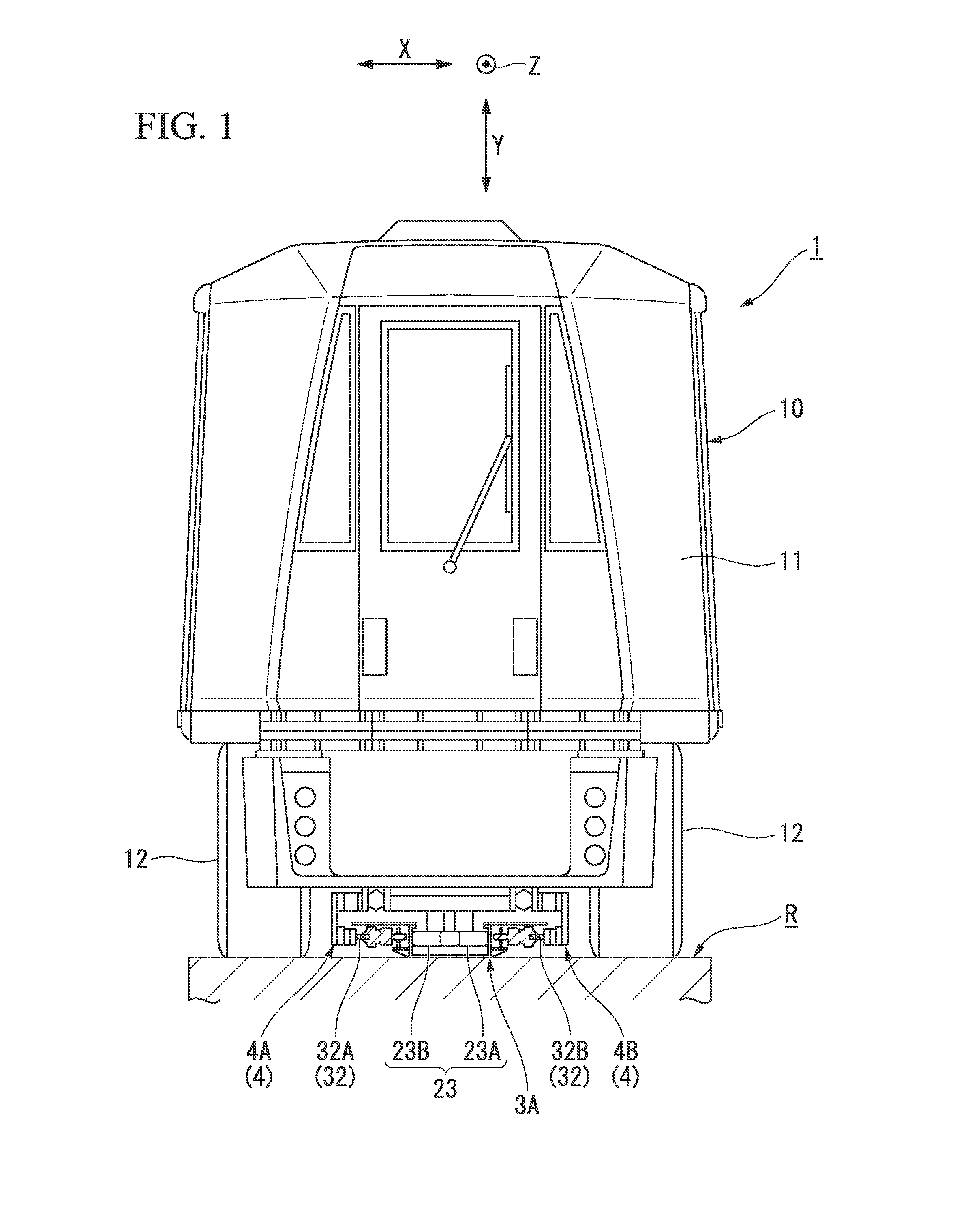
[0036]As illustrated in FIG. 1, a transportation system 1 according to a first embodiment of the present invention adopts a center guide type. The transportation system 1 includes a track-based vehicle 10, and a guide track 3A for guiding a pair of guide wheels 23 (23A and 23B) provided in the track-based vehicle 10 so as to follow a predetermined traveling course by causing the guide wheels to roll.
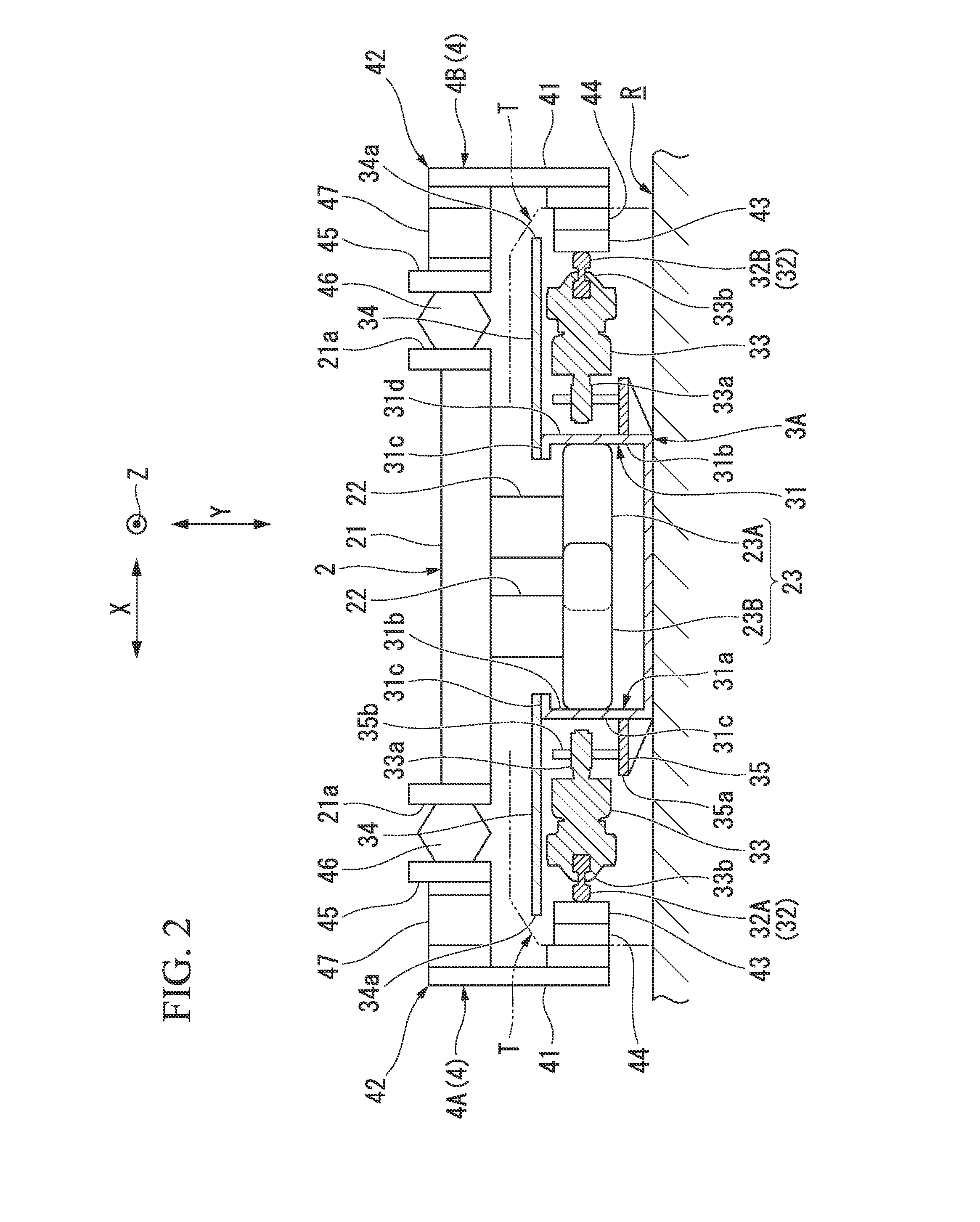
[0037]Herein, in FIGS. 1 and 2, a left and right direction of a plane of paper is referred to as a vehicle width direction X, a direction perpendicular to the plane of paper is referred to as a front and back direction Z, and an up and down direction of the plane of paper is referred to as a vertical direction Y.
[0038]The track-based vehicle 10 includes a vehicle body 11, running wheels 12 and 12 provided at both sides of the vehicle body 11 in the width direction, a guide device 2 configured to guide the vehicle body 11 along the traveling course, and a power collector 4 coming into con...
second embodiment
[0059]As illustrated in FIG. 4, a guide track 3B of a track-based vehicle according to a second embodiment of the present invention has a configuration in which brackets 36 for supporting the conductor rails 32A and 32B are provided at both sides of the guide rail 31, the first insulator 33 is vertically attached to the brackets 36, and the conductor rails 32A and 32B are supported by a conductor rail support end 33b of the first insulator 33.
[0060]Herein, since the configurations of the guide rail 31, the first insulator 33, the positive electric cable 32A, and the negative electric cable 32B are the same as those of the above-mentioned first embodiment, the detailed descriptions thereof will be omitted herein.
[0061]Herein, FIG. 4 is a diagram that illustrates only the guide wheels 23 (23A and 23B) of the guide device while omitting the power collector.
[0062]The bracket 36 is a member for perpendicularly (vertically) attaching the first insulator 33. The bracket 36 is configured to...
third embodiment
[0066]Next, a guide track 3C for a track-based vehicle according to a third embodiment of the present invention illustrated in FIG. 5 has a configuration in which the respective support portions of the positive electric cable 32A and the negative electric cable 32B also serve as insulation plates (protection members).
[0067]That is, the guide track 3C is provided with an accommodation concave portion 38 (a support portion, and a protection member) formed of an insulation material capable of accommodating the conductor rail 32 along both external surfaces 31d of the guide rail 31 (track main body) in the width direction X. The accommodation concave portion 38 forms a U shape when viewed from a cross section, and is placed so that an opening portion 38a side thereof faces outward in the width direction. Moreover, the accommodation concave portion 38 is fixed in a state of being fitted between a pair of brackets 39A and 39B protruding outward in the width direction from two upper and lo...
PUM
Abstract
A guide track (3A) includes a guide rail (31) having a guide groove (31a) opened upward in which the pair of guide wheels (23) inserted, and is formed with a pair of guide surfaces (31b) for causing each of the pair of guide wheels (23) to roll at both sides of the traveling course in a width direction; conductor rails (32) that are placed at both sides of the outside of the traveling course in the width direction with respect to the guide groove (31a) to perform contact electricity supply by pressing a power collection shoe (43) of a power collector (4) of the track-based vehicle; a first insulator (33) that is formed of an insulation material and supports the conductor rails (32) with respect to the guide rail; and insulation plates (34) serving as insulation materials that are provided at both sides of the conductor rail (32) in the width direction, and are provided in parallel to the conductor rail (32) and in parallel to a pressing direction of the power collection shoe (43) so as to prevent a short circuit due to contact with the conductor rail (32) in a vertical direction.
Description
TECHNICAL FIELD[0001]The present invention relates to a guide track for a track-based vehicle used for a track-based new transportation system or the like, and a transportation system. Priority is claimed on Japanese Patent Application No. 2011-042518 filed on Feb. 28, 2011, the contents of which are incorporated herein by reference.BACKGROUND ART[0002]Transportation systems of a center guide type have been known from the related art. In such transportation systems of the center guide type, a power collector for supplying electricity from a conductor rail is attached to a guide device, and is designed and placed so as not approach more than a required insulation separation distance by a relative displacement.[0003]Furthermore, in the case of a direct current type, although there is also a structure in which a positive electric cable is attached to a traveling road side, and a negative electric cable uses a guide rail, a rubber tire type new transportation system generally has a stru...
Claims
Application Information
Patent Timeline
Application Date:The date an application was filed.
Publication Date:The date a patent or application was officially published.
First Publication Date:The earliest publication date of a patent with the same application number.
Issue Date:Publication date of the patent grant document.
PCT Entry Date:The Entry date of PCT National Phase.
Estimated Expiry Date:The statutory expiry date of a patent right according to the Patent Law, and it is the longest term of protection that the patent right can achieve without the termination of the patent right due to other reasons(Term extension factor has been taken into account ).
Invalid Date:Actual expiry date is based on effective date or publication date of legal transaction data of invalid patent.

